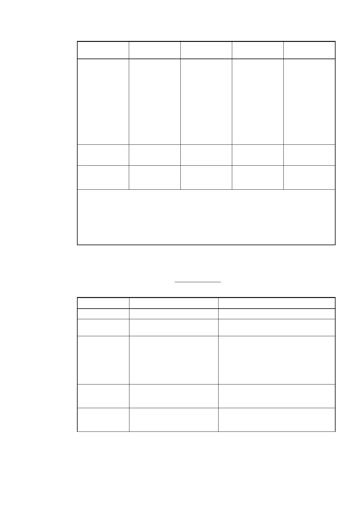
Name Value Internal value Internal value,
type
Default
Behaviour digital
outputs at com-
muncation error
1
)
Off
Last value
Last value 5 sec
Last value 10 sec
Substitute value
Substitute value
5 sec
Substitute value
10 sec
0
1
6
11
2
7
12
BYTE Off
0x00
Substitute value
at output
0...255 00h...FFh BYTE 0
0x00
Detect voltage
overflow at out-
puts
2
)
Off
On
0
1
BYTE Off
0x00
1
) The parameters Behaviour digital outputs at communcation error is only analyzed if the Fail-
safe-mode is ON.
2
) The state "externally voltage detected" appears, if the output of a channel DC0..DC7 should
be switched on while an externally voltage is connected
Ä
Chapter 1.7.5.1.3 “Electrical Con-
nection” on page 944. In this case the start up is disabled, as long as the externally voltage is
connected. The monitoring of this state and the resulting diagnosis message can be disabled
by setting the parameters to "OFF".
1.7.5.1.8 Diagnosis
Structure of the Diagnosis Block via DPM_SLV_DIAG Function Block.
Byte Number Description Possible Values
1 Data length (header included) 7
2 PROFIBUS DP V1 coding:
Vendor specific
129
3 Diagnosis Byte, slot number 31 = CI541-DP (e. g. error at integrated 8
DI / 8 DO)
1 = 1st connected S500 I/O Module
...
10 = 10th connected S500 I/O Module
4 Diagnosis Byte, module
number
According to the I/O Bus specification
passed on by modules to the fieldbus
master
5 Diagnosis Byte, channel According to the I/O Bus specification
passed on by modules to the fieldbus
master
Communication Interface Modules (S500) > PROFIBUS
2019/04/17 3ADR010121, 13, en_US 965