Remarks:
1
)
In AC500 the following interface identifier applies:
14 = I/O bus, 11 = COM1 (e.g. CS31 bus), 12 = COM2.
The PNIO diagnosis block does not contain this identifier.
2
)
With "Device" the following allocation applies:
31 = module itself, 1...10 = decentralized communication interface module
1...10, ADR = hardware address (e. g. of the DC551-CS31)
3
)
With "Module" the following allocation applies depending on the master:
Module error: I/O bus or PNIO: 31 = module itself; COM1/COM2: 1...10 =
expansion 1...10
Channel error: I/O bus or PNIO = module type (2 = DO); COM1/COM2: 1...10 =
expansion 1...10
4
)
In case of module errors, with channel "31 = Module itself" is output.
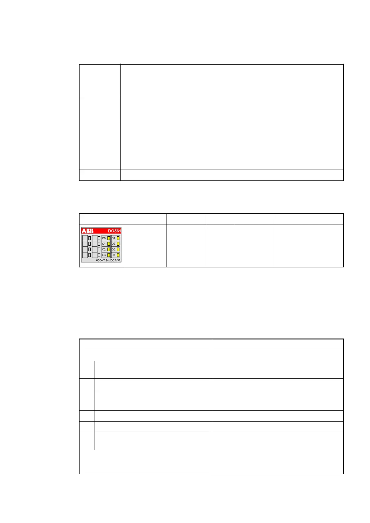
State LEDs
LED State Color LED = OFF LED = ON
Outputs
O0...O7
Digital output Yellow Output is
OFF
Output is ON
(the output voltage is
only displayed if the
supply voltage of the
module is ON)
Technical Data
The System Data of AC500-eCo apply
Ä
Chapter 2.5.1 “System Data AC500-eCo”
on page 1192
Only additional details are therefore documented below.
Parameter Value
Process supply voltage UP
Connections Terminal 19 for UP (+24 VDC) and terminal 20
for ZP (0 VDC)
Rated value 24 VDC
Current consumption via UP terminal 5 mA + max. 0.5 A per output
Max. ripple 5 %
Inrush current
0.000002 A
2
s
Protection against reversed voltage Yes
Rated protection fuse for UP Recommended; the outputs must be pro-
tected by an 3 A fast fuse
Current consumption from 24 VDC power
supply at the L+/UP and M/ZP terminals of the
CPU/bus module
Ca. 10 mA
I/O Modules > Digital I/O Modules
2019/04/173ADR010121, 13, en_US228