Electrical Connection
For a detailed description of the mounting, disassembly and electrical connec-
tion of the module, please refer to the System Assembly, Construction and Con-
nection chapter
Ä
Chapter 2.6 “AC500 (Standard)” on page 1248.
The modules are plugged on an I/O terminal unit
Ä
Chapter 1.4.3 “TU515, TU516, TU516-H
and TU542 for I/O Modules” on page 153. Properly position the modules and press until they
lock in place. The terminal units are mounted on a DIN rail or with 2 screws plus the additional
accessory for wall mounting (TA526
Ä
Chapter 1.8.2.4 “TA526 - Wall Mounting Accessory”
on page 1152).
The electrical connection of the I/O channels is carried out using the 40 terminals of the I/O ter-
minal unit. I/O modules can be replaced without re-wiring the terminal units.
The terminals 1.8, 2.8, 3.8 and 4.8 as well as 1.9, 2.9,3.9 and 4.9 are electrically interconnected
within the I/O terminal units and always have the same assignment, independent of the inserted
module:
Terminals 1.8, 2.8, 3.8 and 4.8: process voltage UP = +24 VDC
Terminals 1.9, 2.9, 3.9 and 4.9: process voltage ZP = 0 VDC
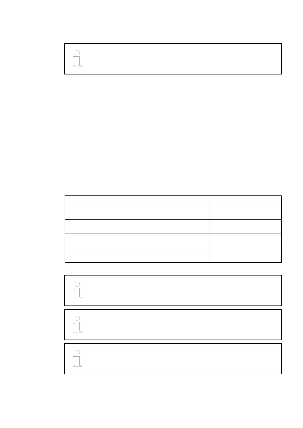
The assignment of the other terminals:
Terminals Signal Description
1.0 to 1.7 I0- to I7- Negative poles of the 8 analog
inputs
2.0 to 2.7 I0+ to I7+ Positive poles of the 8 analog
inputs
3.0 to 3.7 O0- to O7- Negative poles of the 8 analog
outputs
4.0 to 4.7 O0+ to O7+ Positive poles of the 8 analog
outputs
The negative poles of the analog inputs are electrically connected to each other
to form an "Analog Ground" signal for the module.
The negative poles of the analog outputs are electrically connected to each
other to form an "Analog Ground" signal for the module.
There is no galvanic isolation between the analog circuitry and ZP/UP. There-
fore, the analog sensors must be galvanically isolated in order to avoid loops via
the earth potential or the supply voltage.
I/O Modules > Analog I/O Modules
2019/04/173ADR010121, 13, en_US546