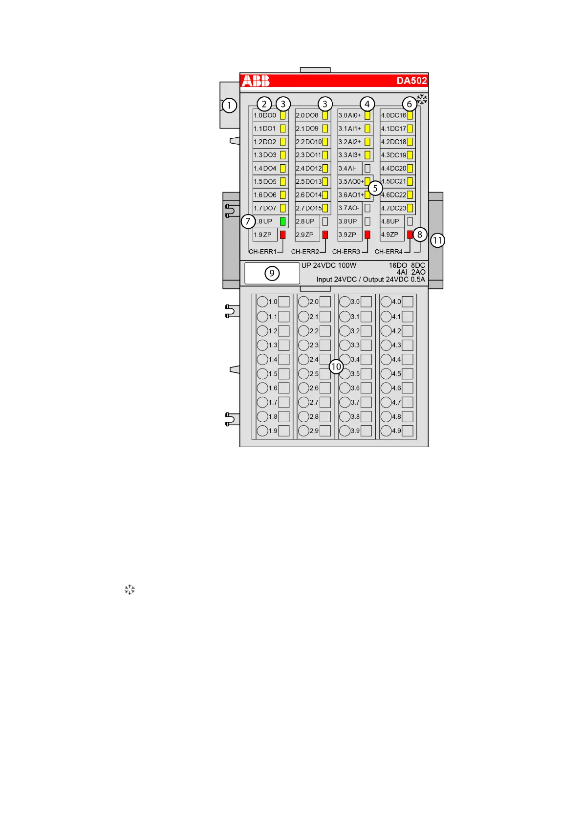
1 I/O bus
2 Allocation between terminal number and signal name
3 16 yellow LEDs to display the signal states of the digital outputs DO0 to DO15
4 4 yellow LEDs to display the signal states of the analog inputs AI0 to AI3
5 2 yellow LEDs to display the signal states of the analog outputs AO0 to AO1
6 8 yellow LEDs to display the signal states of the configurable digital inputs/outputs DC16 to
DC23
7 1 green LED to display the state of the process supply voltage UP
8 4 red LEDs to display errors
9 Label
10 Terminal unit
11 DIN rail
Sign for XC version
Intended Purpose
The device can be used as a decentralized I/O extension module for S500 Communication
Interface Modules (e. g. CI592-CS31, CI501-PNIO, CI541-DP, CI581-CN) or as a centralized
extension module for AC500 CPUs (PM5xx).
I/O Modules > Digital/Analog I/O Modules
2019/04/17 3ADR010121, 13, en_US 603

 Loading...