Cables with PVC core insulation and a core diameter of 0.8 mm can be used up to a length of
ca. 250 m. In this case, the bus terminating resistor is ca. 100 W.
Cables with PE core insulation can be used up to a length of ca. 500 m.
2.6.4.8.3 Bus Topology
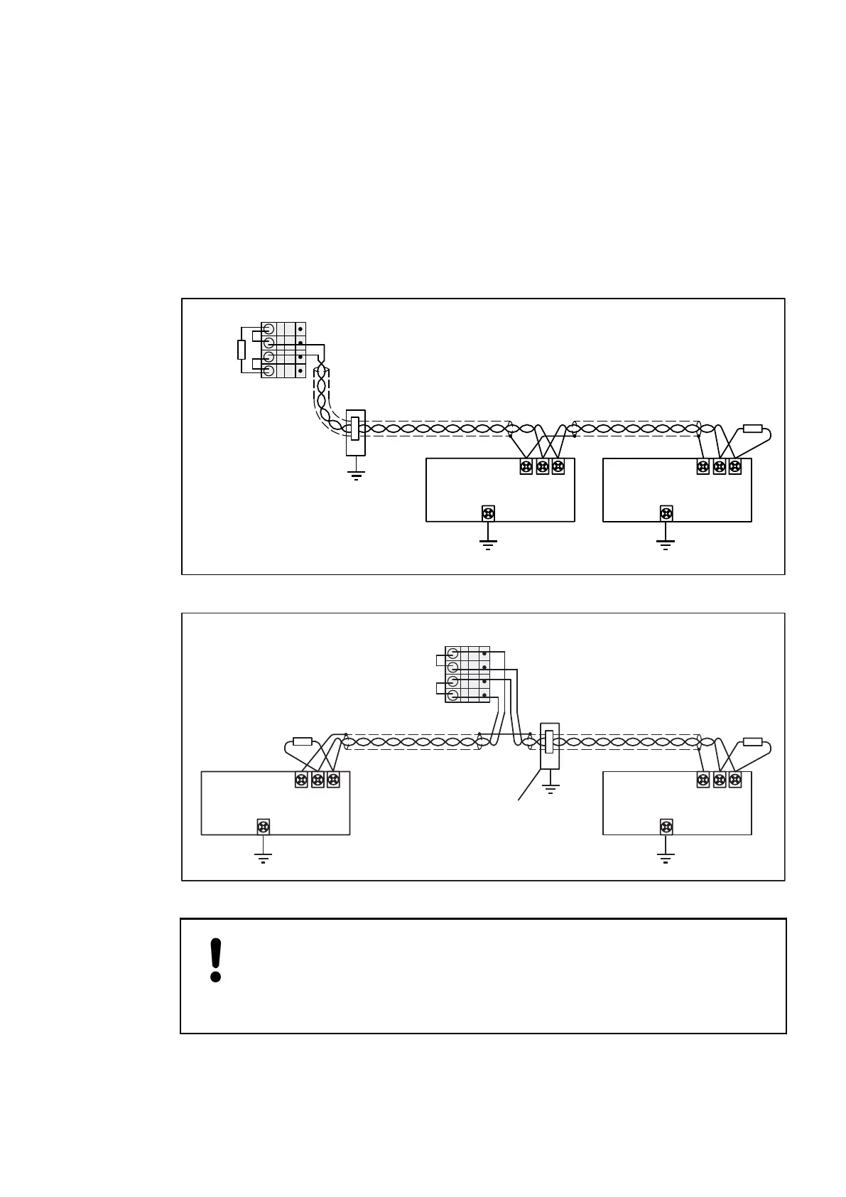
A CS31 system bus always contains only one bus master (CPU or communication module)
which controls all actions on the bus. Up to 31 slaves can be connected to the bus, e.g. remote
modules or slave-configured CPUs. Besides the wiring instructions shown below, the wiring and
earthing instructions provided with the descriptions of the modules are valid additionally.
CS31 system bus
CS31
CS31 bus master
Shield
BUS 2
BUS 1
Shield
BUS 2
BUS 1
slave
CS31
slave
120
Ohms
direct earthing
with clip
on cabinet
steel plate
e.g. PM581
Master at the
bus line end,
pull-up and
pull-down
activated
bus termination
120 Ohms
1
2
3
4
120
Ohms
COM1
Fig. 233: Bus topology for a CS31 system bus at COM1 (bus master at one end of the bus line)
CS31 system bus
CS31
Shield
BUS 2
BUS 1
Shield
BUS 2
BUS 1
slave
CS31
slave
120
Ohms
120
Ohms
direct
earthing
with clip
1
2
3
4
COM1
Master within
the bus line,
pull-up and
pull-down
activated
CS31 bus master
e.g. PM581
Fig. 234: Bus topology for a CS31 system bus at COM1 (bus master within the bus line)
NOTICE!
Risk of malfunctions!
Spur lines are not allowed within the CS31 bus.
Loop the bus line from module to module.
System Assembly, Construction and Connection
AC500 (Standard) > Connection and Wiring
2019/04/173ADR010121, 13, en_US1284