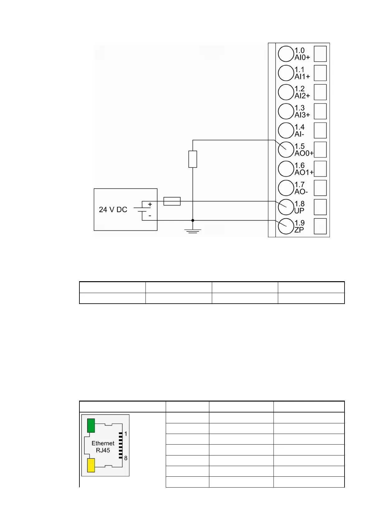
Fig. 185: Connection of analog output loads (current)
The following measuring ranges can be configured
Ä
Chapter 1.7.4.1.7 “Parameterization”
on page 897 and
Ä
Chapter 1.7.4.1.9 “Measuring Ranges” on page 909:
Current 0...20 mA Load 0...500 W 1 channel used
Current 4...20 mA Load 0...500 W 1 channel used
The function of the LEDs is described under Diagnosis and displays / Displays
Ä
Chapter
1.7.4.1.8 “Diagnosis and State LEDs” on page 903.
Unused analog outputs can be left open-circuited.
Assignment of the Ethernet Ports
The terminal unit for the communication interface module provides two Ethernet interfaces with
the following pin assignment:
Table 140: Pin assignment RJ45 jack:
Interface Pin Signal Description
1 TxD+ Transmit data +
2 TxD- Transmit data -
3 RxD+ Receive data +
4 NC not used
5 NC not used
6 RxD- Receive data -
7 NC not used
Communication Interface Modules (S500) > Modbus
2019/04/17 3ADR010121, 13, en_US 895