CAUTION!
Risk of damaging the processor module!
– Never short-circuit or overload the outputs.
– Never connect inductive loads without an external suppression against
voltage peaks due to inductive kickback.
– Never connect voltages > 240 V. All outputs must be fed from the same
phase.
– Use an external 5 A fast protection fuse for the outputs.
1.2.1.2.4 Internal Data Exchange
Parameter Value
Digital inputs (bytes) 1
Digital outputs (bytes) 1
1.2.1.2.5 I/O Configuration
The configuration data of the onboard I/Os is stored in the processor podule PM55x.
1.2.1.2.6 Parameterization
For information about parameterization, refer to the description for onboard I/Os for processor
podule PM55x AC500-eCo Onboard I/Os.
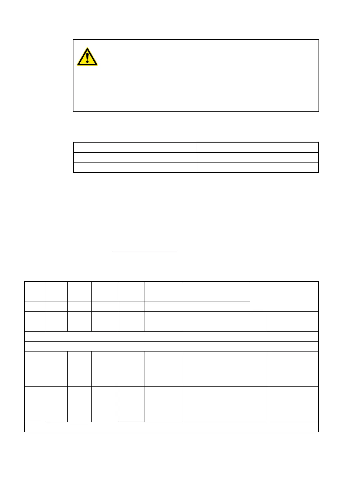
1.2.1.2.7 Diagnosis
E1...E
4
d1 d2 d3 d4 Identifier
000...063
AC500-Display <− Display in
Class Comp Dev Mod Ch Err PS501 PLC Browser
Class Inter-
face
Device Module Channel Error-
Identifier
Error message Remedy
Errors for Onboard I/O
Light errors
3 8 255 2 0 3 MaxWaitRun for onboard I/O
module has expired, when PLC
is put into RUN state
Reboot and try it
again. If the error
still exists, replace
processor module
for testing
3 8 255 3 0 26 Invalid configuration of onboard
I/O module, e. g. 2 input chan-
nels are configured as fast
counter and interrupt input at
the same time.
Correct PLC con-
figuration
Warnings
Processor Modules > AC500-eCo
2019/04/173ADR010121, 13, en_US44