3
)
With "Module" the following allocation applies depending on the master:
Module error: I/O bus or FBP: 31 = module itself; COM1/COM2: 1...10 = expan-
sion 1...10
Channel error: I/O bus or FBP = module type (4 = DC); COM1/COM2: 1...10 =
expansion 1...10
4
)
In case of module errors, with channel "31 = module itself" is output.
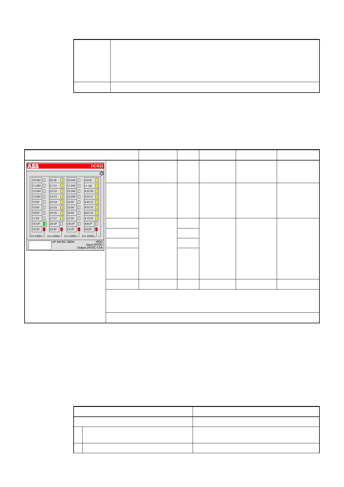
State LEDs
During the power ON procedure, the module initializes automatically. All LEDs (except the
channel LEDs) are ON during this time.
LED State Color LED = OFF LED = ON LED flashes
Inputs/
outputs
C0...C15
Digital input
or digital
output
Yellow Input/output
= OFF
Input/output =
ON
1
)
--
UP Process
supply
voltage
24 VDC via
terminal
Green Process
supply
voltage is
missing
Process
supply voltage
OK
--
CH-ERR1 Channel
Error, error
messages in
groups (dig-
ital inputs/
outputs com-
bined into the
groups 1, 2,
3, 4)
Red No error or
process
supply
voltage is
missing
Severe error
within the cor-
responding
group
Error on one
channel of the
corresponding
group (e.g.
short circuit at
an output)
CH-ERR2 Red
CH-ERR3 Red
CH-ERR4 Red
CH-ERR
2
)
Module error Red -- Internal error --
1
) Indication LED is ON even if an input signal is applied to the channel and the
supply voltage is off. In this case the module is not operating and does not gen-
erate an input signal.
2
) All of the LEDs CH-ERR1 to CH-ERR4 light up together
Technical Data
The System Data of AC500 and S500
Ä
Chapter 2.6.1 “System Data AC500” on page 1248 are
valid for standard version.
The System Data of AC500-XC
Ä
Chapter 2.7.1 “System Data AC500-XC” on page 1309 are
valid for the XC version.
Only additional details are therefore documented below.
Parameter Value
Process supply voltage UP
Connections Terminals 1.8, 2.8, 3.8 and 4.8 for +24 V (UP)
as well as 1.9, 2.9, 3.9 and 4.9 for 0 V (ZP)
Rated value 24 VDC
I/O Modules > Digital I/O Modules
2019/04/17 3ADR010121, 13, en_US 305