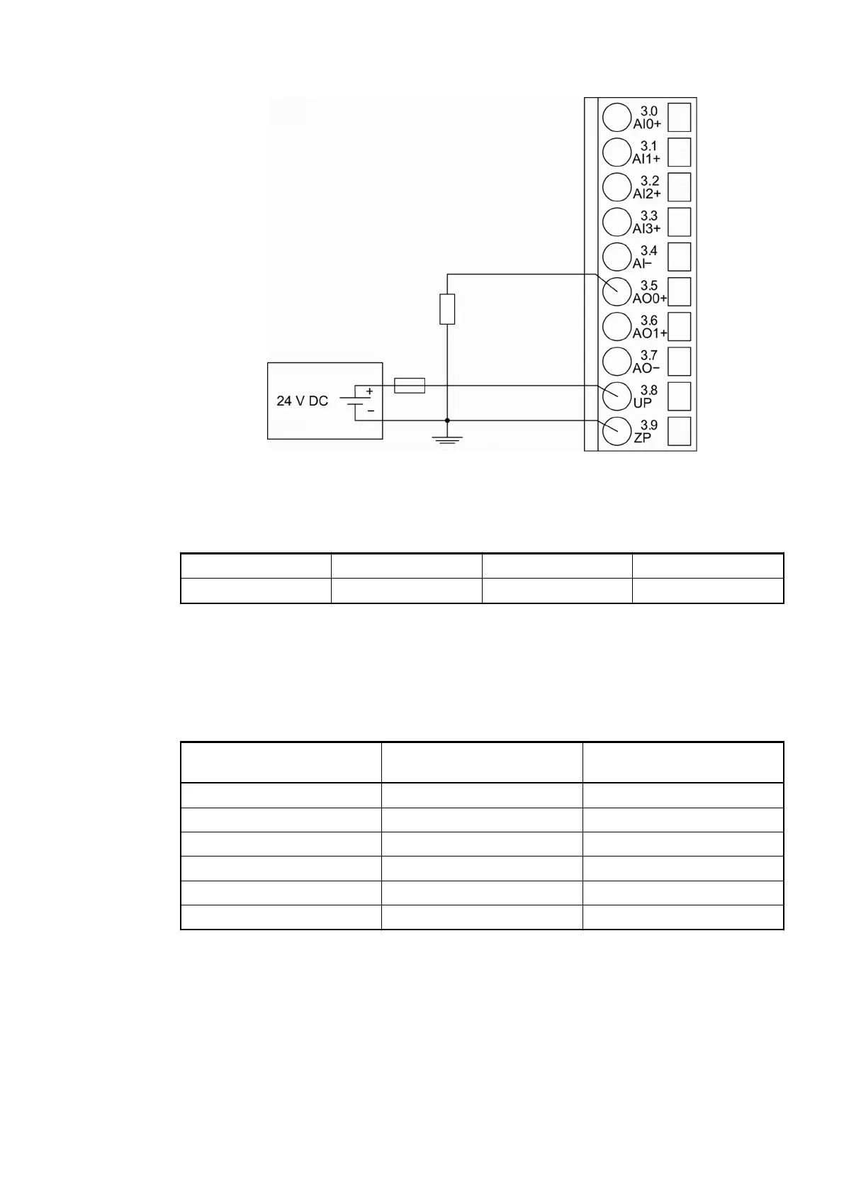
Fig. 103: Connection of analog output loads (current)
The following measuring ranges can be configured
Ä
Chapter 1.5.3.1.2.6 “Parameterization”
on page 618
Ä
Chapter 1.5.3.1.2.9 “Measuring Ranges” on page 625:
Current 0 mA...20 mA Load 0 W...500 W 1 channel used
Current 4 mA...20 mA Load 0 W...500 W 1 channel used
For a description of the function of the LEDs, please refer to Diagnosis and displays / Displays
Ä
Chapter 1.5.3.1.2.8 “State LEDs” on page 625.
Unused analog outputs can be left open-circuited.
Internal Data Exchange
Without the Fast Counter With the Fast Counter (only
with AC500)
Digital inputs (bytes) 3 5
Digital outputs (bytes) 1 3
Analog inputs (words) 4 4
Analog outputs (words) 2 2
Counter input data (words) 0 4
Counter output data (words) 0 8
I/O Configuration
The module itself does not store configuration data. It draws its parameterization data from the
master device of the I/O bus (CPU or bus module) during power-up of the system.
Hence, replacing I/O modules is possible without any re-parameterization via software.
I/O Modules > Digital/Analog I/O Modules
2019/04/17 3ADR010121, 13, en_US 617