NOTICE!
Risk of faulty measurements!
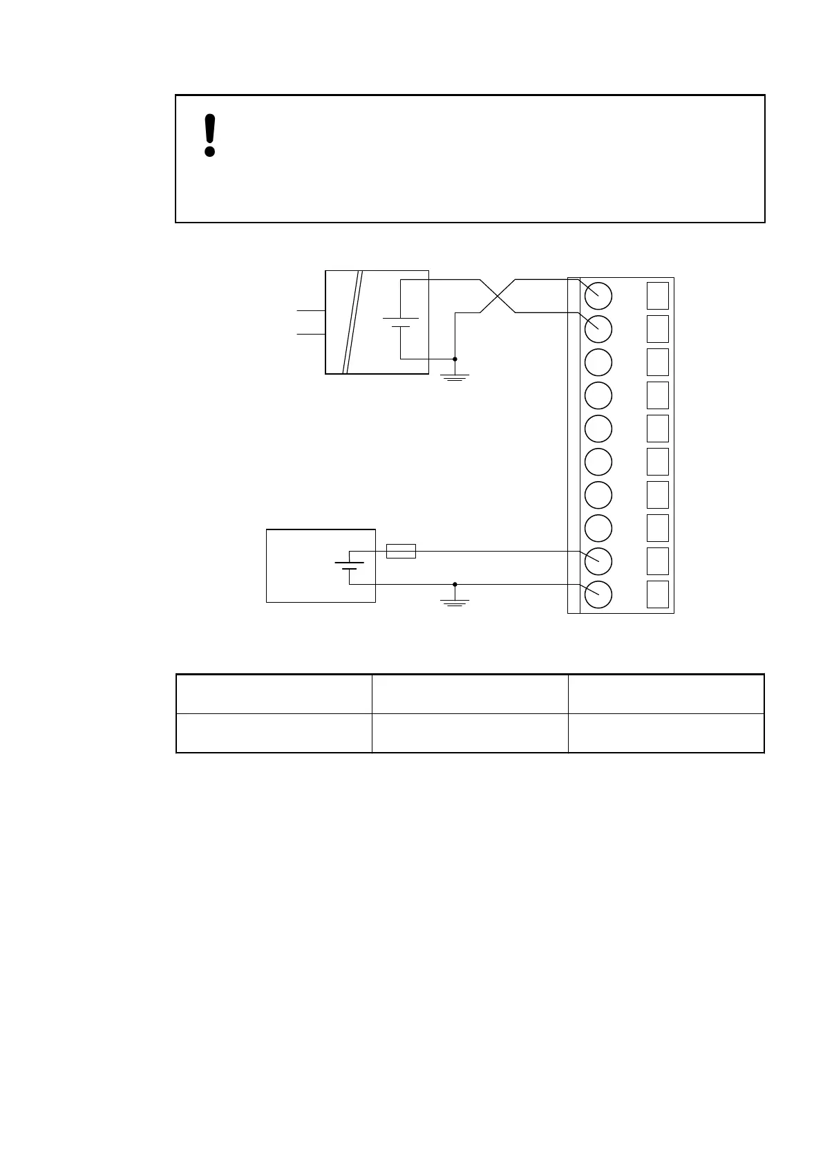
The negative pole/earthing potential at the sensors must not have too large a
potential difference with respect to ZP (max. ± 1 V within the full signal range).
Make sure that the potential difference never exceeds ± 1 V.
The following figure shows the connection of active-type analog sensors (voltage) to differential
analog inputs AI0 and AI1. Proceed with AI2 and AI3 in the same way.
2.0
AI0+
2.1
AI1+
2.2
AI2+
2.3
AI3+
2.4
AI-
2.5
AO0+
2.6
AO1+
2.7
AO-
2.8
UP
2.9
ZP
24 V DC
-
+
+
-
U
IN
Fig. 125: Connection of active-type analog sensors (voltage) to differential analog inputs
Voltage 0...10 V with differential inputs, 2 chan-
nels used
Voltage -10 V...+10 V with differential inputs, 2 chan-
nels used
For the measuring ranges that can be configured, please refer to the sections Measuring
Ranges
Ä
Chapter 1.7.1.2.10 “Measuring Ranges” on page 731 and Parameterization
Ä
Chapter 1.7.1.2.7 “Parameterization” on page 721.
To avoid error messages, configure unused analog input channels as "unused".
Use of Analog Inputs as Digital Inputs
Several (or all) analog inputs can be configured as digital inputs . The inputs are not electrically
isolated against the other analog channels.
The following figure shows the connection of digital sensors to the analog input AI0. Proceed
with the analog inputs AI1 to AI3 in the same way.
Communication Interface Modules (S500) > CANopen
2019/04/173ADR010121, 13, en_US718