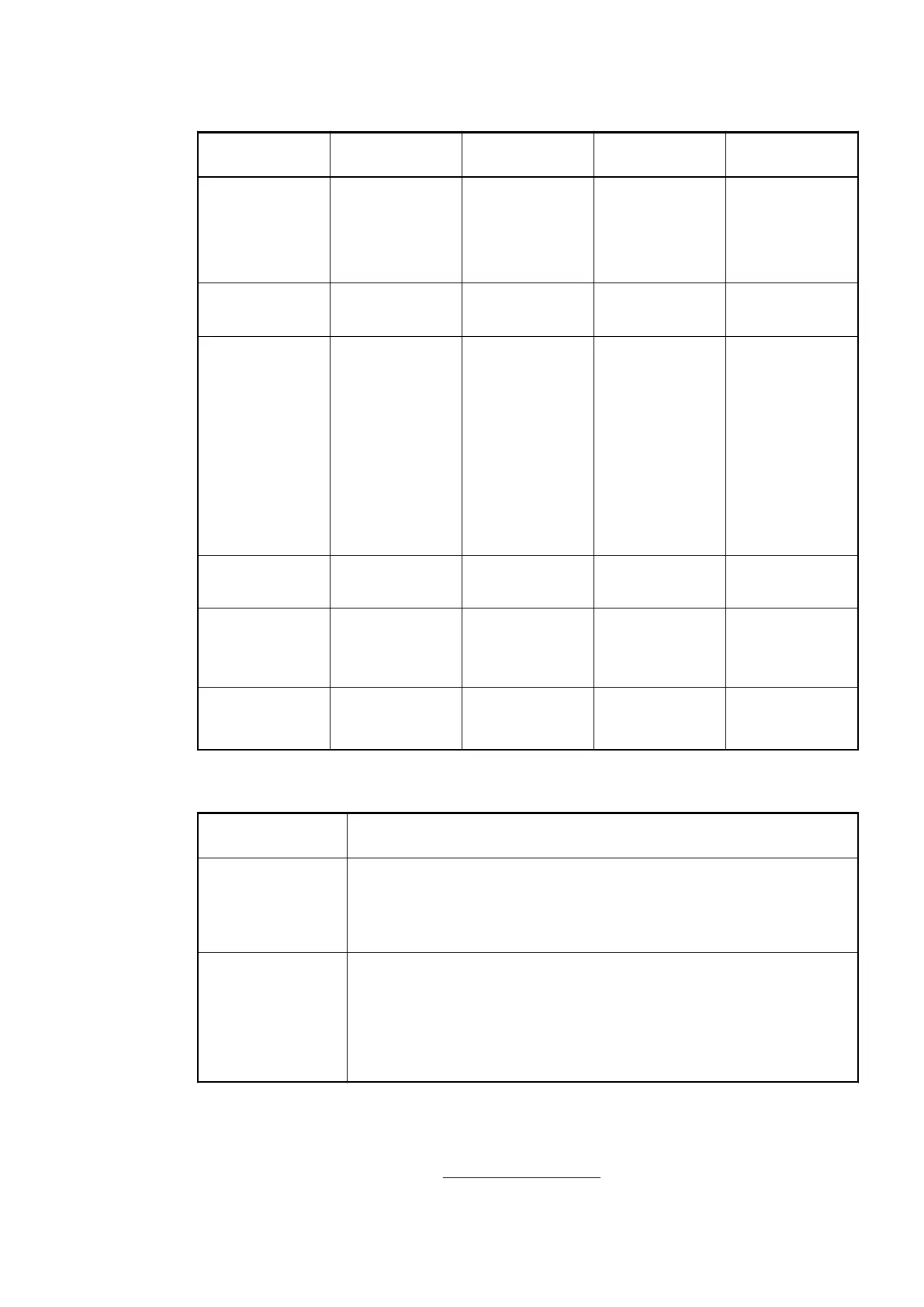
Group Parameters for the Digital Part
Name Value Internal value Internal value,
type
Default
Input delay 0.1 ms
1 ms
8 ms
32 ms
0
1
2
3
BYTE 0.1 ms
0x00
Detect short cir-
cuit at outputs
Off
On
0
1
BYTE On
0x01
Behavior DO at
comm. error
1
)
Off
Last value
Last value 5 sec
Last value 10 sec
Substitute value
Substitute value
5 sec
Substitute value
10 sec
0
1
6
11
2
7
12
BYTE Off
0x00
Substitute value
at output
0 ... 65535 0000h ... FFFFh WORD 0
0x0000
Preventive
voltage feedback
monitoring for
DC0..DC7
2
)
Off
On
0
1
BYTE Off
0x00
Detect voltage
overflow at out-
puts
3
)
Off
On
0
1
BYTE Off
0x00
Remarks:
1
)
The parameter Behavior DO at comm. error is applied to DC and DO
channels and only analyzed if the failsafe mode is ON.
2
)
The state "externally voltage detected" appears if the output of a channel
DC0..DC7 is to be switched on while an external voltage is connected.
In this case, start-up is disabled while the externally voltage is con-
nected. The monitoring of this state and the resulting diagnosis message
can be disabled by setting the parameters to "OFF".
3
)
The error state "voltage overflow at outputs" appears if external voltage
at digital outputs DC0..DC7 and DO0..DO7 has exceeded the process
supply voltage UP3 (see Electrical Connection
Ä
Chapter 1.7.1.3.3
“Electrical Connection” on page 740). The according diagnosis message
"Voltage overflow on outputs " can be disabled by setting the parameters
to "OFF". This parameter should only be disabled in exceptional cases
as voltage overflow may produce reverse voltage.
1.7.1.3.8 Diagnosis
Structure of the diagnosis block via CANOM_NODE_DIAG
Communication Interface Modules (S500) > CANopen
2019/04/173ADR010121, 13, en_US750