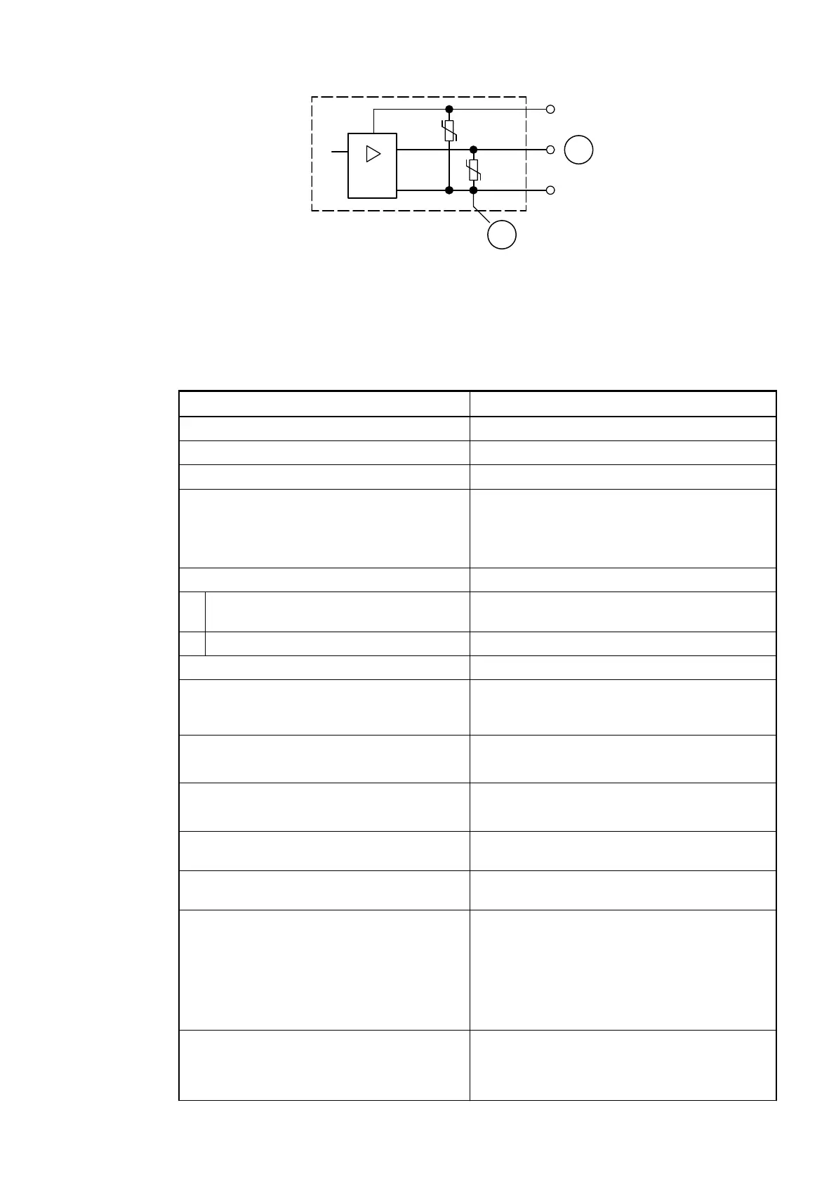
Fig. 169: Digital input/output (circuit diagram)
1 Digital output
2 Varistors for demagnetization when inductive loads are turned off
Technical Data of the Analog Inputs
Parameter Value
Number of channels per module 4
Distribution of channels into groups 1 group with 4 channels
Connection if channels AI0+ to AI3+ Terminals 1.0 to 1.3
Reference potential for AI0+ to AI3+ Terminal 1.4 (AI-) for voltage and RTD meas-
urement
Terminals 1.9, 2.9 and 3.9 for current measure-
ment
Input type
Unipolar Voltage 0 V...10 V, current or Pt100/Pt1000/
Ni1000
Bipolar Voltage -10 V...+10 V
Electrical isolation Against Ethernet network
Configurability 0 V...10 V, -10 V...+10 V, 0/4 mA...20 mA,
Pt100/1000, Ni1000 (each input can be config-
ured individually)
Channel input resistance Voltage: > 100 kW
Current: ca. 330 W
Time constant of the input filter Voltage: 100 µs
Current: 100 µs
Indication of the input signals 1 LED per channel (brightness depends on the
value of the analog signal)
Conversion cycle 1 ms (for 4 inputs + 2 outputs); with RTDs Pt/
Ni... 1 s
Resolution Range 0...10 V: 12 bits
Range -10...+10 V: 12 bits + sign
Range 0...20 mA: 12 bits
Range 4...20 mA: 12 bits
Range RTD (Pt100, PT1000, Ni1000): 0.1 °C
Conversion error of the analog values
caused by non-linearity, adjustment error at
factory and resolution within the normal
range
Typ. 0.5 %, max. 1 %
Communication Interface Modules (S500) > EtherCAT
2019/04/17 3ADR010121, 13, en_US 857