2.0
AI0+
2.1
AI1+
2.2
AI2+
2.3
AI3+
2.4
AI-
2.5
AO0+
2.6
AO1+
2.7
AO-
2.8
UP
2.9
ZP
24 V DC
-
+
Pt100
Pt1000
Ni1000
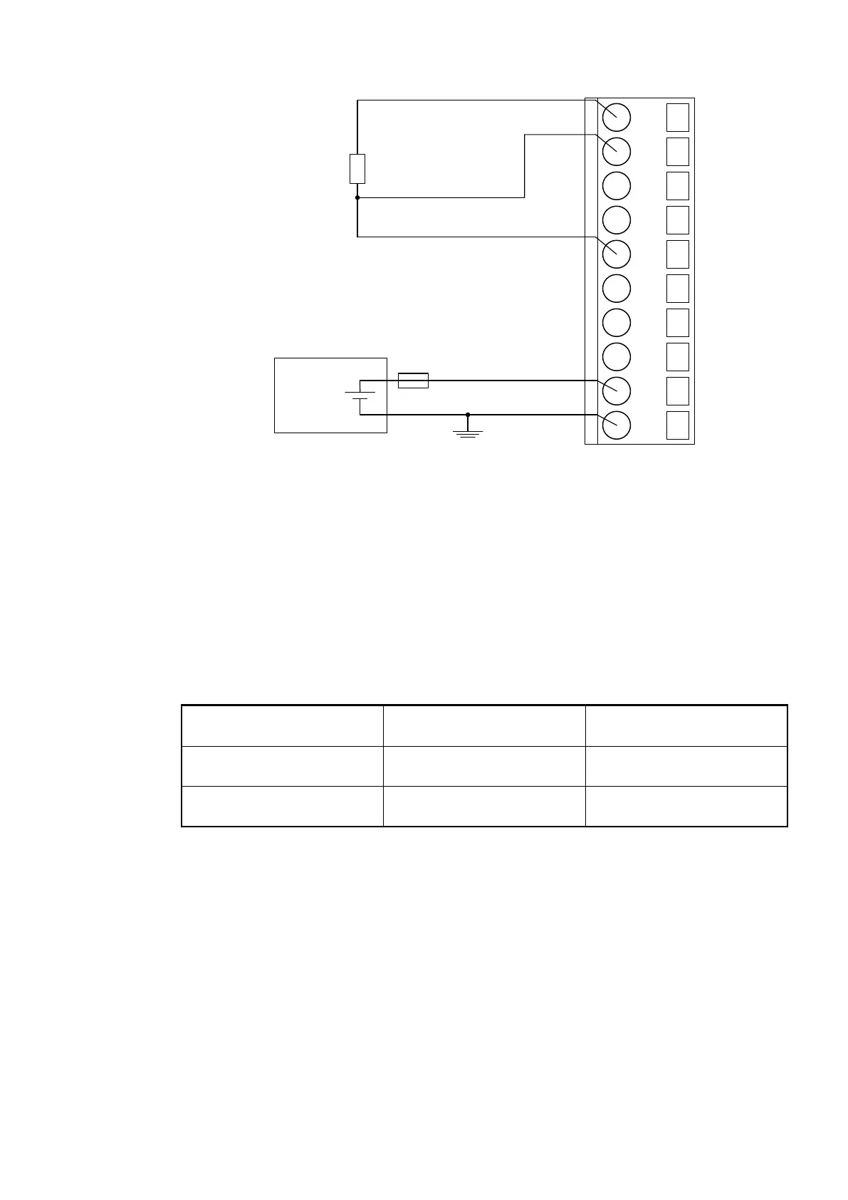
With 3-wire configuration, 2 adjacent analog channels belong together (e. g. the channels 0 and
1). In this case, both channels are configured according to the desired operating mode. The
lower address must be the even address (channel 0), the next higher address must be the odd
address (channel 1).
The constant current of one channel flows through the resistance thermometer. The constant
current of the other channel flows through one of the cores. The module calculates the meas-
ured value from the two voltage drops and stores it under the input with the higher channel
number (e. g. I1).
In order to keep measuring errors as small as possible, it is necessary to have all the involved
conductors in the same cable. All the conductors must have the same cross section.
The following measuring ranges can be configured
Ä
Chapter 1.7.5.1.7 “Parameterization”
on page 960 :
Pt100 -50 °C...+400 °C 3-wire configuration, 2 chan-
nels used
Pt1000 -50 °C...+400 °C 3-wire configuration, 2 chan-
nels used
Ni1000 -50 °C...+150 °C 3-wire configuration, 2 chan-
nels used
The function of the LEDs is described under Diagnosis and displays / Displays
Ä
Chapter
1.7.5.1.9 “State LEDs” on page 970.
The module CI541-DP performs a linearization of the resistance characteristic.
To avoid error messages from unused analog input channels, configure them as "unused".
Connection of Active-type Analog Sensors (Voltage) with Electrically Isolated Power Supply to the Analog
Inputs
The following figure shows the connection of active-type analog sensors (voltage) with electri-
cally isolated power supply to the analog input AI0. Proceed with the analog inputs AI1 to AI3 in
the same way.
Communication Interface Modules (S500) > PROFIBUS
2019/04/173ADR010121, 13, en_US952