NOTICE!
Risk of faulty measurements!
The negative pole/earthing potential at the sensors must not have too large a
potential difference with respect to ZP (max. ± 1 V within the full signal range).
Make sure that the potential difference never exceeds ± 1 V.
CAUTION!
The process supply voltage must be included within the earthing concept of the
plant (e. g. earthing of the minus pole).
The module provide several diagnosis functions
Ä
Chapter 1.7.3.1.8 “Diagnosis” on page 848.
The measuring ranges are described in the section Measuring Ranges
Ä
Chapter 1.7.3.1.7
“Parameterization” on page 842
Ä
Chapter 1.7.3.1.10 “Measuring Ranges” on page 851.
The function of the LEDs is described in the section State LEDs
Ä
Chapter 1.7.3.1.8 “Diag-
nosis” on page 848.
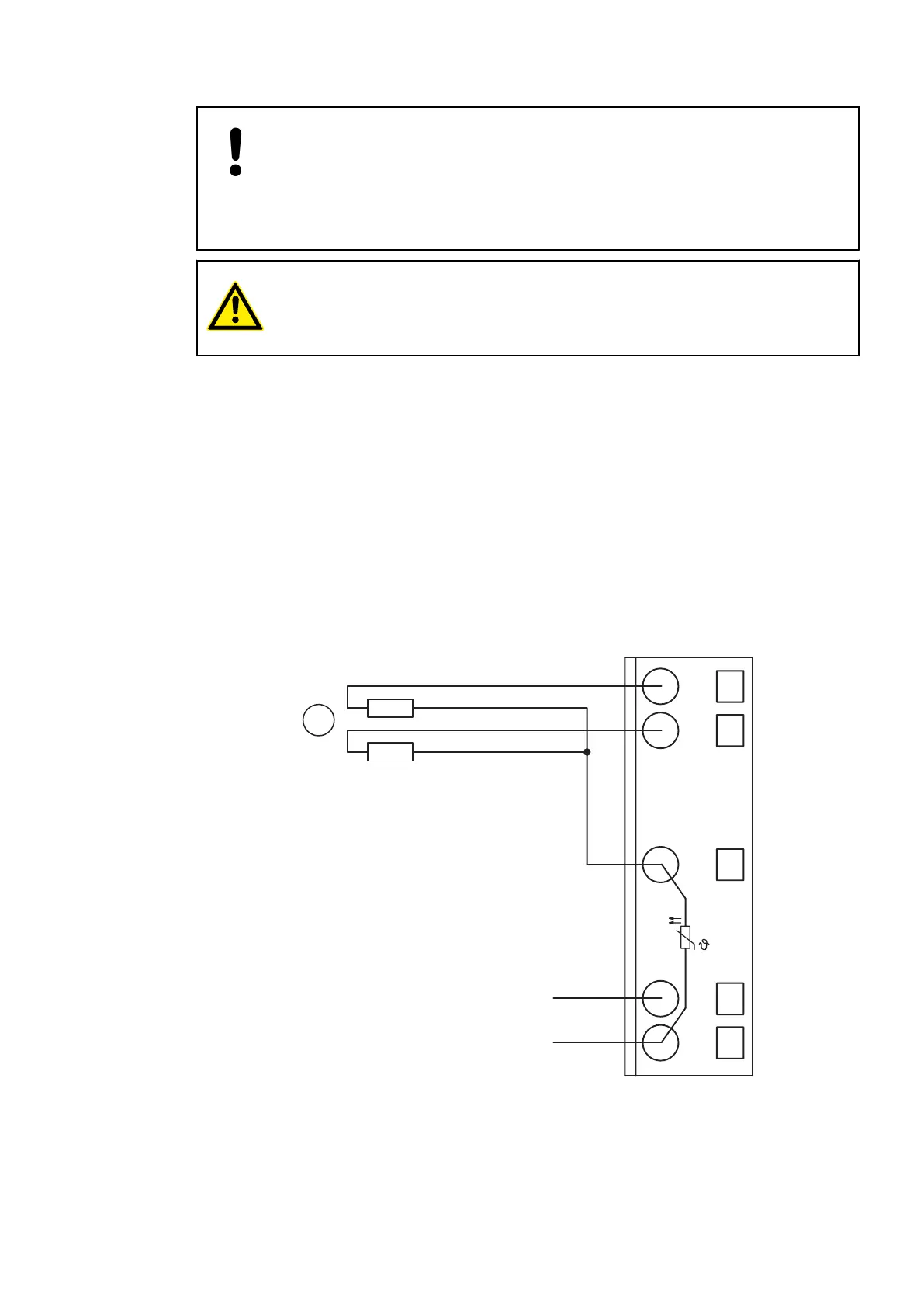
Connection of Resistance Thermometers in 2-wire Configuration
When resistance thermometers (Pt100, Pt1000, Ni1000) are used, a constant current must flow
through them to build the necessary voltage drop for the evaluation. For this, the module CI511-
ETHCAT provides a constant current source which is multiplexed over the max. 4 analog input
channels.
The following figure shows the connection of resistance thermometers in 2-wire configuration.
1.0
1.1
1.8
1.9
AI0+
AI1+
UP
ZP
UP
ZP
PTC
1.5
AI–
1
Fig. 160: Connection of resistance thermometers in 2-wire configuration
1 Pt100 (2-wire), Pt1000 (2-wire), Ni1000 (2-wire); 1 analog sensor requires 1 channel
Communication Interface Modules (S500) > EtherCAT
2019/04/173ADR010121, 13, en_US832