For the open-circuit detection (cut wire), each channel is pulled up to "plus" by a
high-resistance resistor. If nothing is connected, the maximum voltage will be
read in then.
Analog signals are always laid in shielded cables. The cable shields are earthed at both ends of
the cables. In order to avoid unacceptable potential differences between different parts of the
installation, low resistance equipotential bonding conductors must be laid.
For simple applications (low disturbances, no high requirement on precision), the shielding can
also be omitted.
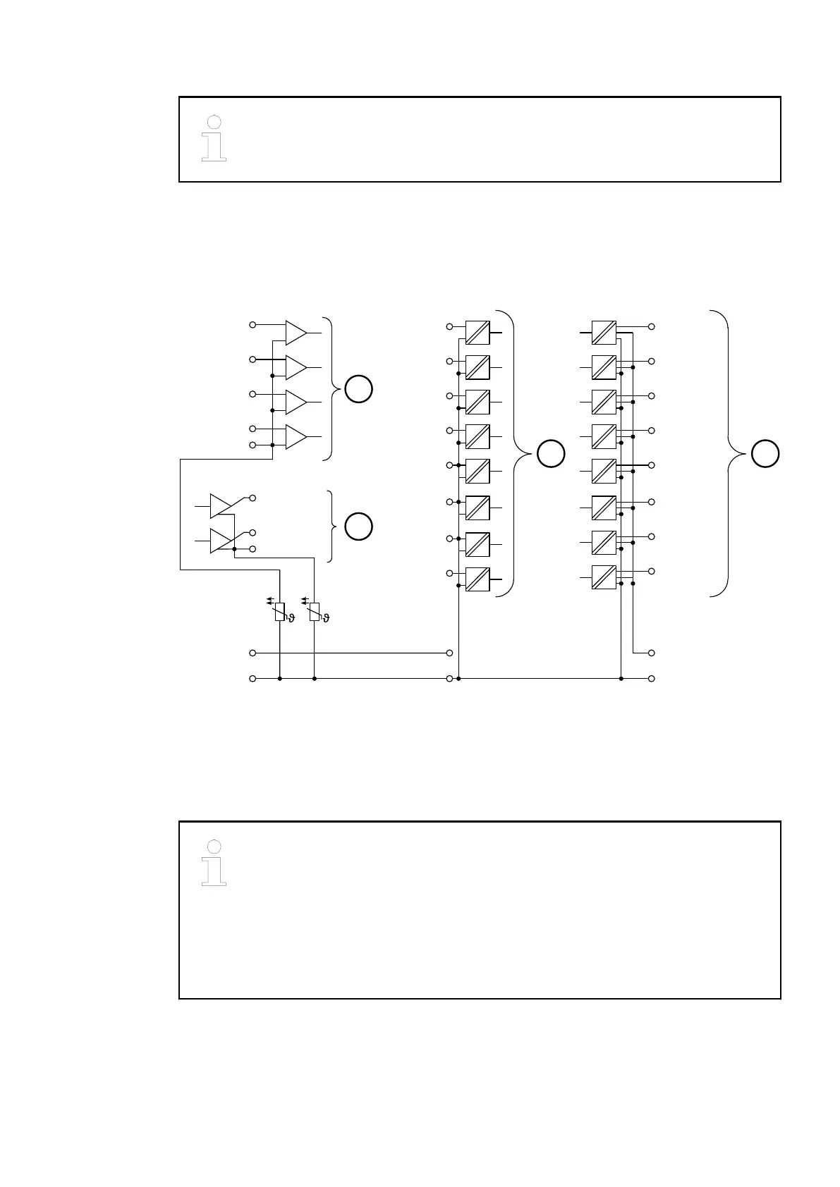
The following figures show the electrical connection of the Ethernet bus module CI511-ETHCAT.
+
−
+
−
+
−
+
−
+
−
+
−
PTC
AI 0+
AI 1+
AI 2+
AI 3+
AI −
AGND
1.0
1.1
1.2
1.3
1.4
PTC
1.5
1.6
1.7
AO 0+
AO 1+
AO −
3.0 DO 0
3.1 DO 1
3.2 DO 2
3.3 DO 3
3.4 DO 4
3.5 DO 5
3.6 DO 6
3.7 DO 7
DI 0 2.0
DI 1 2.1
DI 2 2.2
DI 3 2.3
DI 4 2.4
DI 5 2.5
DI 6 2.6
DI 7 2.7
1.8
1.9
UP +24 V
ZP 0 V
2.8
2.9 3.9
3.8
UP3 +24 V
ZP 0 V
1
2
3 4
Fig. 159: Connection of the bus module CI511-ETHCAT
1 4 analog inputs, configurable for 0...10 V, -10...+10 V, 0/4...20 mA, Pt100/Pt1000, Ni1000
and digital signals
2 2 analog outputs, configurable for -10...+10 V, 0/4...20 mA
3 8 digital inputs 24 VDC
4 8 digital outputs 24 VDC, 0.5 A max.
In case of voltage feedback, 2 cases are distinguished:
1. The outputs are already active
The output group will be switched off. A diagnosis message will appear. After 5
seconds, the module tries automatic reactivation.
2. The outputs are not active
Only the output with voltage feedback will not be set to active. A diagnosis mes-
sage will appear.
Communication Interface Modules (S500) > EtherCAT
2019/04/17 3ADR010121, 13, en_US 831