4.0 DO8
4.1 DO9
4.2 DO10
4.3 DO11
4.4 DO12
4.5 DO13
4.6 DO14
4.7 DO15
DI8 3.0
DI9 3.1
DI10 3.2
DI11 3.3
DI12 3.4
DI13 3.5
DI14 3.6
DI15 3.7
2.8
2.9
UP +24 V
ZP 0 V
3.8
3.9 4.9
4.8
UP3 +24 V
ZP 0 V
DC0 2.0
DC1 2.1
DC2 2.2
DC3 2.3
DC4 2.4
DC5 2.5
DC6 2.6
DC7 2.7
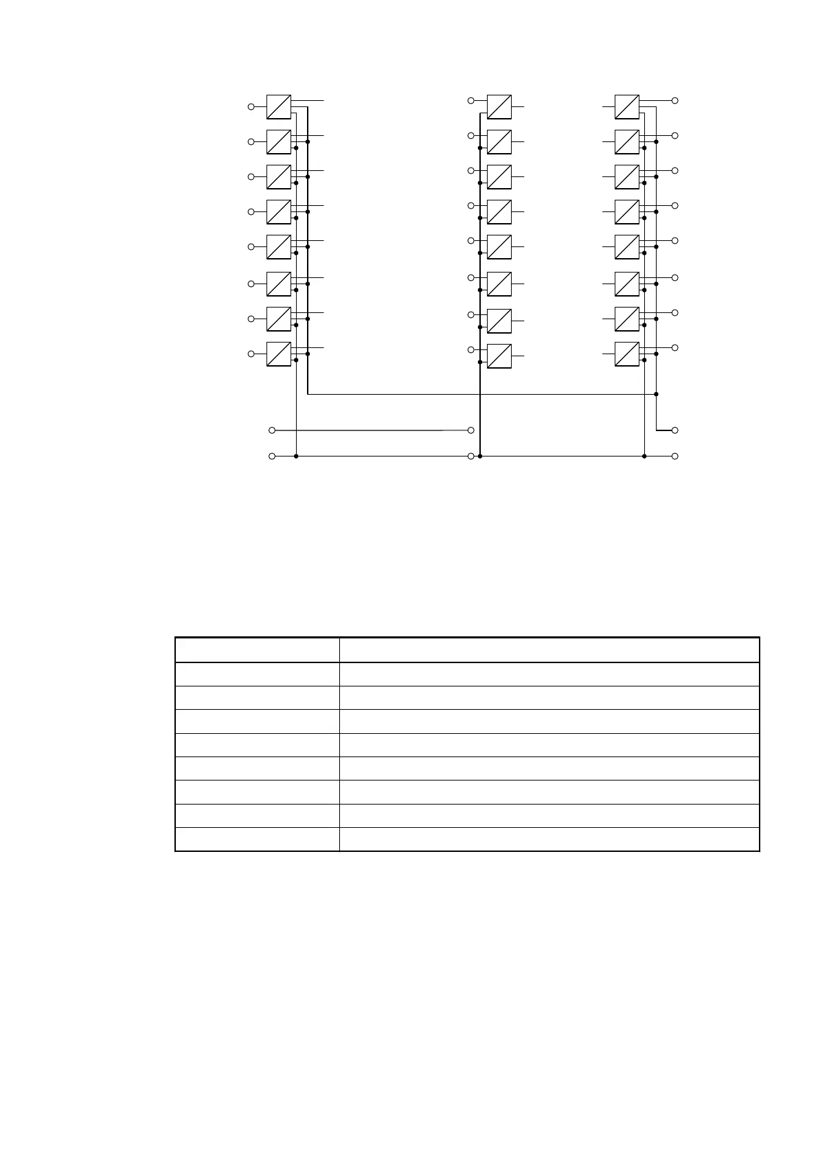
Fig. 132: Connection of the bus module CI582-CN
For a description of the meaning of the LEDs, please refer to the section for the state LEDs
Ä
Chapter 1.7.1.3.9 “State LEDs” on page 754.
The maximum possible bus length of a CAN network depends on bit rate (transmission rate)
and cable type. The sum of all bus segments must not exceed the maximum bus length
Bit Rate (speed) Bus Length
1 Mbit/s 40 m
800 kbit/s 50 m
500 kbit/s 100 m
250 kbit/s 250 m
125 kbit/s 500 m
62.5 kbit/s 1000 m
20 kbit/s 2500 m
10 kbit/s 5000 m
Connection of the Digital Inputs
The following figure shows the electrical connection of the digital input DI8. Proceed with the
digital inputs DI9 to DI15 in the same way.
Bus Length
Communication Interface Modules (S500) > CANopen
2019/04/173ADR010121, 13, en_US746