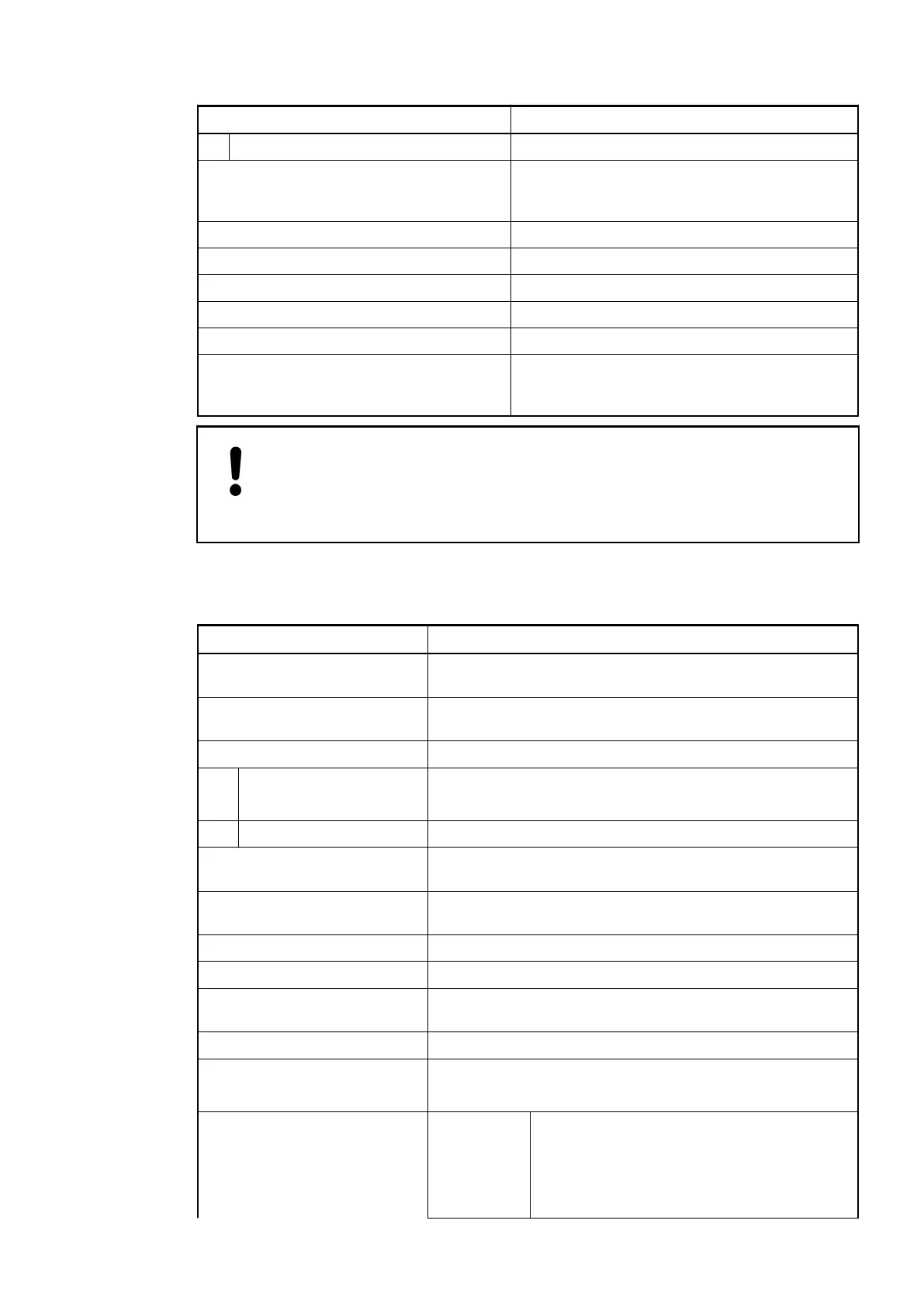
Parameter Value
Protection fuse for L+ Recommended
Current consumption from 24 VDC power
supply at the terminals UP/L+ and ZP/M of
the CPU/Bus Module
Ca. 5 mA
Galvanic isolation No
Surge-voltage (max.) 35 VDC for 0.5 s
Max. power dissipation within the module 4.9 W
Weight Ca. 120 g
Mounting position Horizontal or vertical
Cooling The natural convection cooling must not be hin-
dered by cable ducts or other parts in the switch-
gear cabinet.
NOTICE!
Attention:
All I/O channels (digital and analog) are protected against reverse polarity,
reverse supply, short circuit and continuous overvoltage up to 30 VDC.
Technical Data of the Analog Inputs
Parameter Value
Number of channels per
module
4 individually configurable voltage or current inputs
Distribution of channels into
groups
1 (4 channels per group)
Resolution
Unipolar Voltage: 0 V...+5 V; 0 V...+10 V: 12 bits
Current 0 mA...20 mA; 4 mA...20 mA: 12 bits
Bipolar Voltage -2.5 V...+2.5 V; -5 V...+5 V: 11 bits plus sign
Connection of the signals I0- to
I3-
Terminals 3, 6, 9, 12
Connection of the signals I0+ to
I3+
Terminals 2, 5, 8, 11
Input type Differential
Galvanic isolation No galvanic isolation between the inputs and the I/O bus
Common mode input range Signal voltage plus common mode voltage must be within
±12 V
Indication of the input signals No
Channel input resistance Voltage: >1 MW
Current: ca. 250 W
Conversion error of the analog
values caused by non-linearity,
adjustment error at factory and
resolution within the normal
range
Typ. ±0.5 % of full scale (voltage)
±0.5 % of full scale (current 0 mA...20 mA)
±0.7 % of full scale (current 4 mA...20 mA)
at 25 °C
I/O Modules > Analog I/O Modules
2019/04/17 3ADR010121, 13, en_US 449