● Terminals 1.0, 2.0 and 3.0: process supply voltage UP = +24 VDC
● Terminals 1.0, 2.1 and 3.1: process supply voltage ZP = 0 V
The assignment of the bus system terminals depends on the inserted PROFINET communica-
tion interface module (see Ethernet communication interface modules overview).
1.4.5.1 Technical Data
The System Data of AC500 and S500
Ä
Chapter 2.6.1 “System Data AC500” on page 1248 are
valid for standard version.
The System Data of AC500-XC
Ä
Chapter 2.7.1 “System Data AC500-XC” on page 1309 are
valid for the XC version.
Only additional details are therefore documented below.
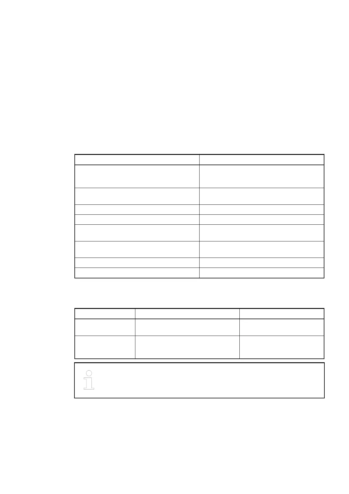
Parameter Value
Ethernet 10/100 base-TX or 100 base-TX (depending
on the plugged CI5xx module), 2x RJ45
socket
Number of bus system connectors 3 (the type of bus system depends on the
PROFINET I/O bus module)
Rated voltage 24 VDC
Max. permitted total current 10 A via the supply terminals (UP and ZP)
Earthing Direct connection to the earthed DIN rail or via
the screws with wall mounting
Spring terminals Front terminal, conductor connection vertically
with respect to the printed circuit board
Weight 200 g
Mounting position Horizontal or vertical
1.4.5.2 Ordering Data
Part No. Description Product Life Cycle Phase *)
1SAP 214 400
R0001
TU520-ETH, PROFINET I/O terminal
unit, 24 VDC, spring terminals
Active
1SAP 414 400
R0001
TU520-ETH-XC, PROFINET I/O
terminal unit, 24 VDC, spring
terminals, XC version
Active
*) For planning and commissioning of new installations use modules in Active
status only.
1.4.6 TU531 and TU532 for I/O Modules
● TU531, I/O terminal unit, 230 VAC, screw terminals
● TU532, I/O terminal unit, 230 VAC, spring terminals
● TU532-XC, I/O terminal unit, 230 VAC, spring terminals, XC version
Terminal Units (AC500 Standard) > TU531 and TU532 for I/O Modules
2019/04/173ADR010121, 13, en_US164