EasyManuals Logo

ABB AC500 PLC User Manual

ABB AC500 PLC
1315 pages
To Next Page IconTo Next Page
To Previous Page IconTo Previous Page
Page #923 background imageLoading...
Page #923 background image
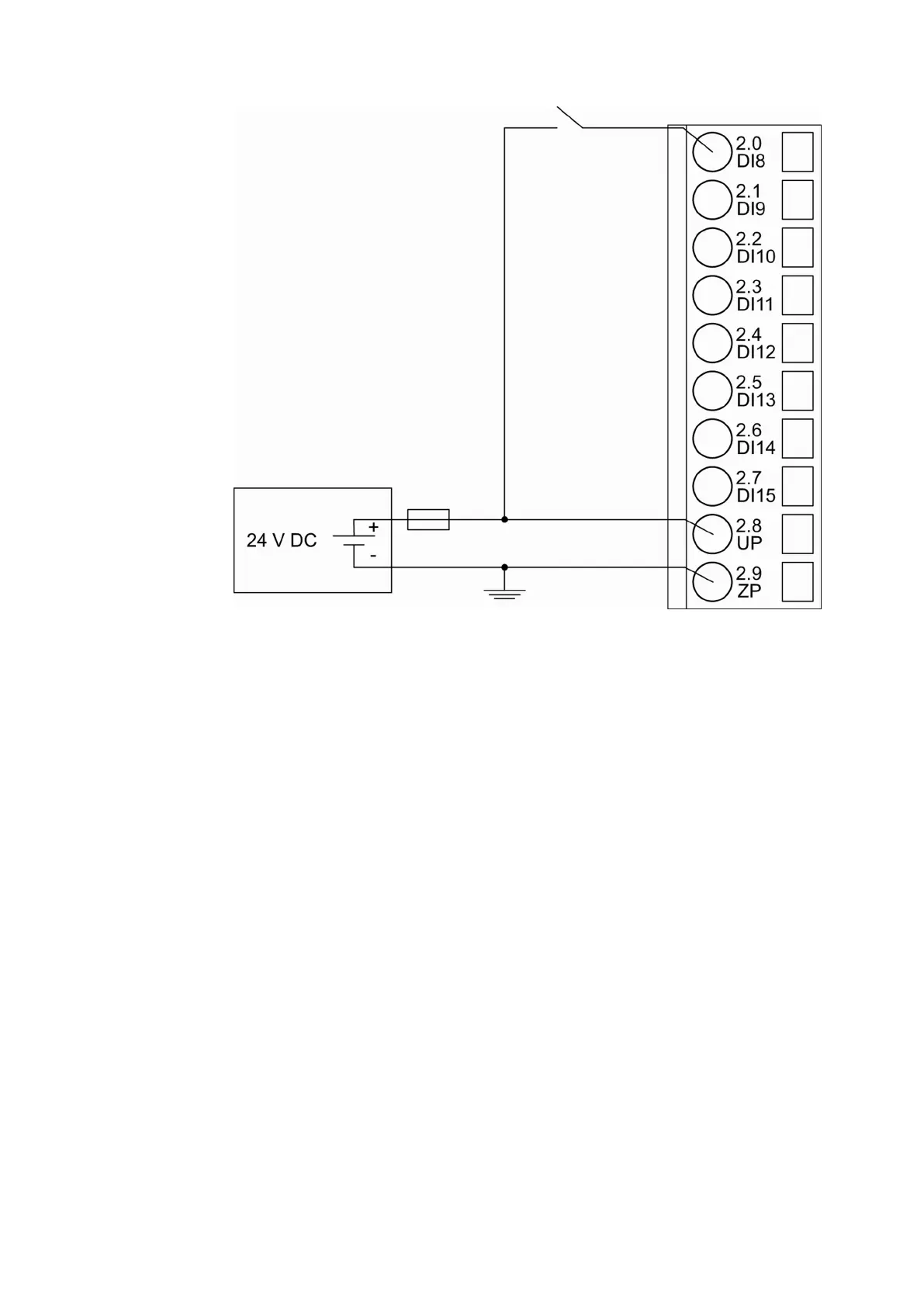
Fig. 188: Connection of the digital inputs to the module CI522-MODTCP
The meaning of the LEDs is described in Displays
Ä
Chapter 1.7.4.2.8.1 “State LEDs”
on page 934.
Connection of the Digital Outputs
The following figure shows the electrical connection of the digital output DO8. Proceed with the
digital outputs DO9 - DO15 in the same way.
Device Specifications
Communication Interface Modules (S500) > Modbus
2019/04/17 3ADR010121, 13, en_US 923

Table of Contents

Questions and Answers:

Question and Answer IconNeed help?

Do you have a question about the ABB AC500 PLC and is the answer not in the manual?

ABB AC500 PLC Specifications

General IconGeneral
Digital InputsUp to 1024
Digital OutputsUp to 1024
Real-time clockYes
Power Supply24 V DC
Protection ClassIP20
ProcessorARM based
Programming LanguagesIEC 61131-3 (LD, ST, FBD, SFC, IL)
Operating Temperature-25°C to +70°C
Communication InterfacesEthernet, CAN, RS-232, RS-485

Related product manuals