To avoid error messages from unused analog input channels, configure them as "unused".
Use of Analog Inputs as Digital Inputs
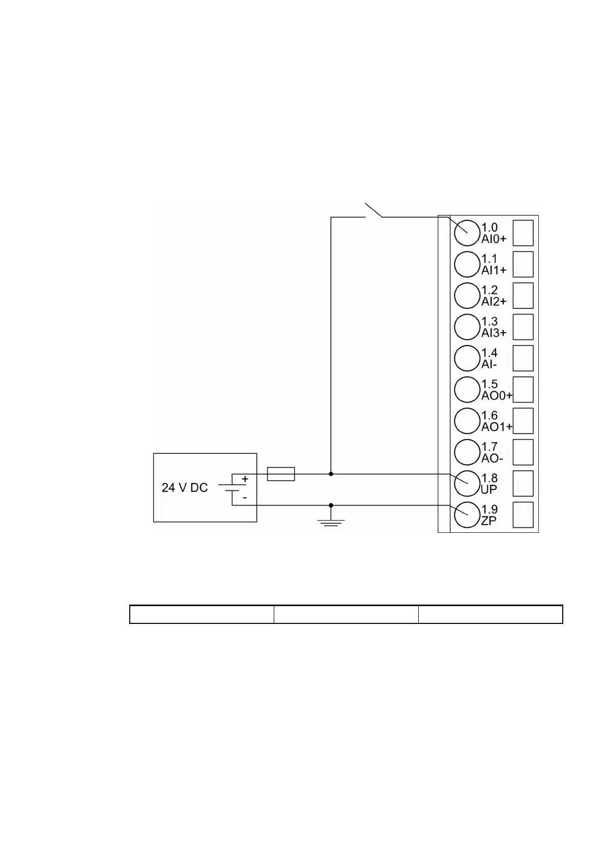
Several (or all) analog inputs can be configured as digital inputs
Ä
Chapter 1.7.4.1.10.5 “Tech-
nical Data of the Analog Inputs if used as Digital Inputs” on page 915. The inputs are not elec-
trically isolated against the other analog channels.
The following figure shows the connection of digital sensors to the analog input AI0. Proceed
with the analog inputs AI1 to AI3 in the same way.
Fig. 183: Use of analog inputs as digital inputs
The following measuring ranges can be configured
Ä
Chapter 1.7.4.1.7 “Parameterization”
on page 897 and
Ä
Chapter 1.7.4.1.9 “Measuring Ranges” on page 909 :
Digital input 24 V 1 channel used
The function of the LEDs is described under Diagnosis and displays / Displays
Ä
Chapter
1.7.4.1.8 “Diagnosis and State LEDs” on page 903.
Connection of Analog Output Loads (Voltage)
The following figure shows the connection of output loads to the analog output AO0. Proceed
with the analog output AO1 in the same way.
Communication Interface Modules (S500) > Modbus
2019/04/17 3ADR010121, 13, en_US 893