Connection of Active-type Analog Sensors (voltage) with Electrically Isolated Power Supply to the Analog
Inputs
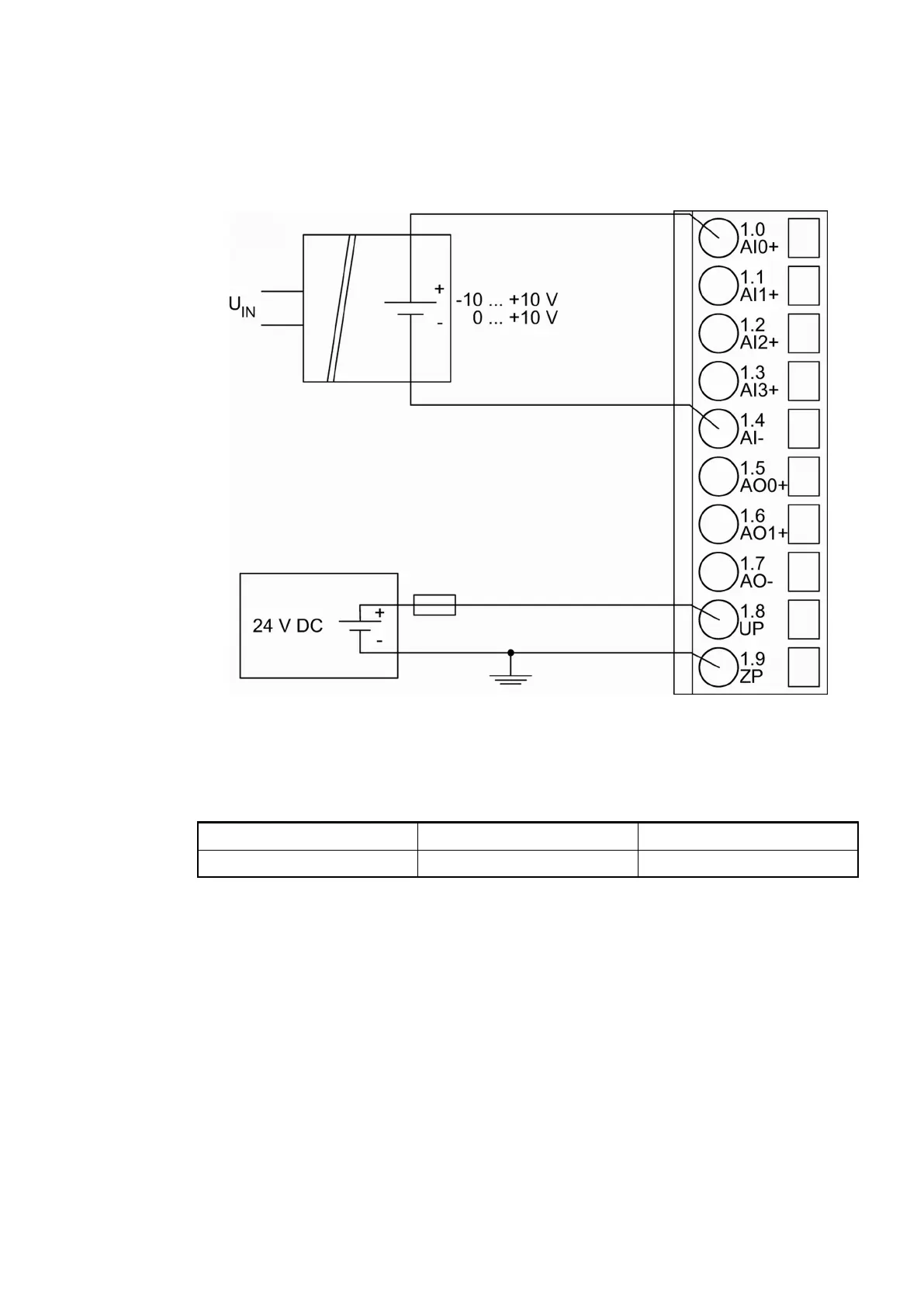
The following figure shows the connection of active-type analog sensors (voltage) with electri-
cally isolated power supply to the analog input AI0. Proceed with the analog inputs AI1 to AI3 in
the same way.
Fig. 178: Connection of active-type analog sensors (voltage) with electrically isolated power
supply to the analog inputs
The following measuring ranges can be configured
Ä
Chapter 1.7.4.1.7 “Parameterization”
on page 897 and
Ä
Chapter 1.7.4.1.9 “Measuring Ranges” on page 909:
Voltage 0...10 V 1 channel used
Voltage -10 V...+10 V 1 channel used
The function of the LEDs is described under Diagnosis and displays / Displays
Ä
Chapter
1.7.4.1.8 “Diagnosis and State LEDs” on page 903.
To avoid error messages from unused analog input channels, configure them as "unused".
Connection of Active-type Analog Sensors (Current) with Electrically Isolated Power Supply to the Analog
Inputs
The following figure shows the connection of active-type analog sensors (current) with electri-
cally isolated power supply to the analog input AI0. Proceed with the analog inputs AI1 to AI3 in
the same way.
Communication Interface Modules (S500) > Modbus
2019/04/173ADR010121, 13, en_US888