Terminal Signal Description
1.7 TermA Bus termination data line A
1.8 DGND Reference potential for data transmission
1.9 DGND Reference potential for data transmission
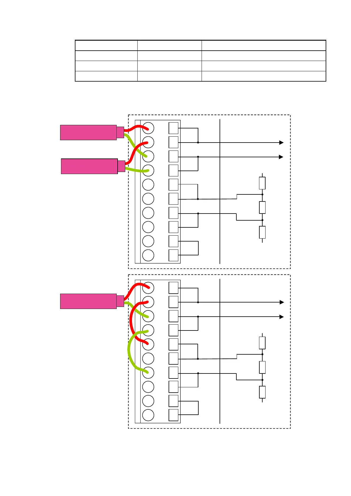
At the line ends of a bus segment, termination resistors must be connected. If using TU517/
TU518, the bus termination resistors can be enabled by connecting the terminals TermA and
TermB to the data lines A and B (no external termination resistors are required, see illustration
below).
1.0
1.1
1.2
1.3
1.4
1.5
1.6
1.7
1.8
1.9
+5 V DC
GND
PROFIBUS in
PROFIBUS out
1.0
1.1
1.2
1.3
1.4
1.5
1.6
1.7
1.8
1.9
+5 V DC
GND
PROFIBUS end
Communication Interface Modules (S500) > PROFIBUS
2019/04/173ADR010121, 13, en_US946
 Loading...


