I0+ 11
I0− 12
O0+ 10
+
−
O1+ 13
I1+ 14
−−− 16
SG 17
I1− 15
UP 19
ZP 20
SG 18
+
−
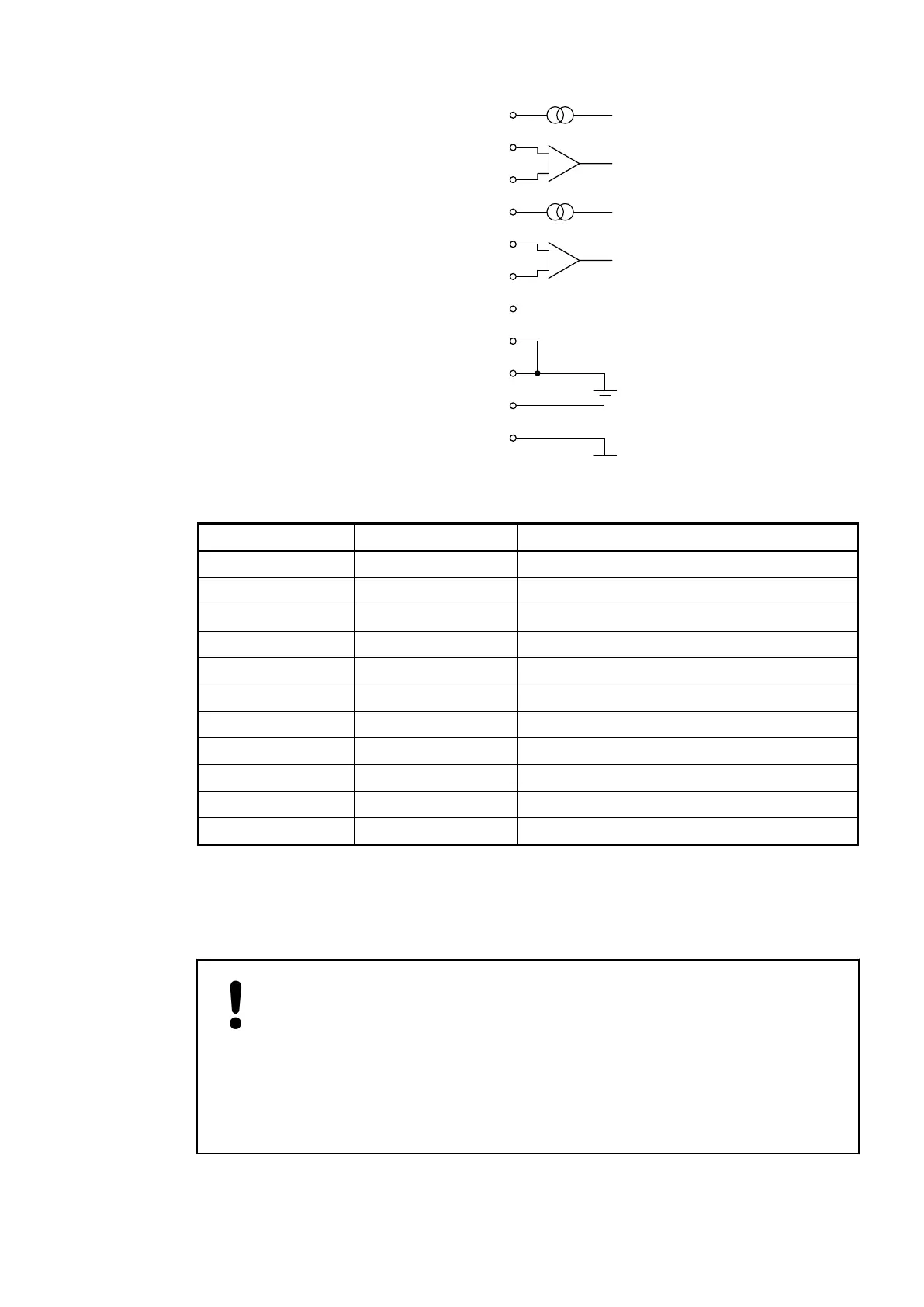
The assignment of the terminals:
Terminal Signal Description
10 O0+ Current source of channel 0
11 I0+ Sense input of channel 0
12 I0- Return input of channel 0
13 O1+ Current source of channel 1
14 I1+ Sense input of channel 1
15 I1- Return input of channel 1
16 --- Reserved
17 SG Signal ground
18 SG Signal ground
19 UP Process voltage UP (24 VDC)
20 ZP Process voltage ZP (0 VDC)
The internal power supply voltage for the module's circuitry is carried out via the I/O bus (pro-
vided by a bus module or a CPU). Thus, the current consumption from 24 VDC power supply at
the terminals L+/UP and M/ZP of the CPU/bus module increases by 5 mA per AI562.
The external power supply connection is carried out via the UP (+24 VDC) and the ZP (0 VDC)
terminals.
NOTICE!
Risk of imprecise and faulty measurements!
Analog signals may be distorted seriously by external electromagnetic influ-
ences.
Use shielded wires when wiring analog signal sources. The cable shield must
be grounded at both ends of the cable. Provide a potential equalisation of a low
resistance to avoid high potential differences between different parts of the
plant.
I/O Modules > Analog I/O Modules
2019/04/173ADR010121, 13, en_US408