NOTICE!
The internal power supply voltage, which is connected to pin 6 of the D-sub
connector, must not be short-circuited or connected to any other voltages.
The optional serial COM2 interface provides communication via RS-485 and is carried out as a
removable 5-pin terminal with screw connection. The COM2 interface can be used
● for online connection with Automation Builder software (via a RS-485 programming cable. e.
g. TK504
Ä
Chapter 1.8.1.9 “TK504 - Programming Cable” on page 1127
● as Modbus RTU (master and slave)
● for ASCII serial protocols
The serial RS-485 interface is not electrically isolated using TA562-RS or
TA562-RS-RTC.
Using TA569-RS-ISO the RS-485 serial interface has galvanic isolation.
Communication via CS31 bus is not possible.
Additional information for installing the accessory modules can be found in
Ä
Chapter 1.8.1.4
“TA562-RS - Serial RS-485 Adaptor” on page 1112,
Ä
Chapter 1.8.1.5 “TA569-RS-ISO - Serial
RS-485 Isolated Adaptor” on page 1113 and
Ä
Chapter 1.8.1.6 “TA562-RS-RTC - Adaptor with
Serial RS-485 (COM2) and Real-time Clock ” on page 1114.
Additional information for wiring the COM2 interface can be found in serial interface COM2
(PM55x, PM56x)
Ä
Chapter 2.5.4.3 “Serial Interface COM2” on page 1212.
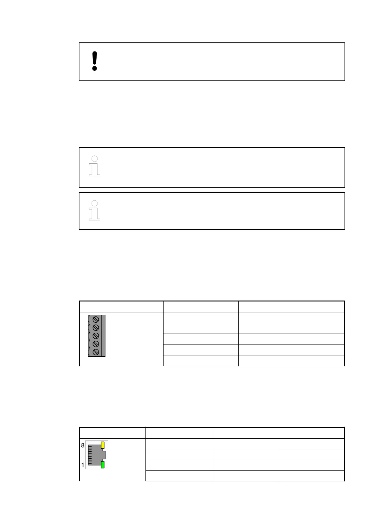
Table 5: Pin assignment
Serial Interface Pin Description
1 Terminator P
2 TxD/RxD-P
3 TxD/RxD-N
4 Terminator N
5 Functional earth
The Ethernet interface is carried out via a RJ45 jack. The pin assignment of the Ethernet inter-
face:
Interface Pin Description
1 Tx+ Transmit Data +
2 Tx- Transmit Data -
3 Rx+ Receive Data +
4 NC Not connected
Serial interface
COM2 (optional)
Ethernet inter-
face
Processor Modules > AC500-eCo
2019/04/173ADR010121, 13, en_US26