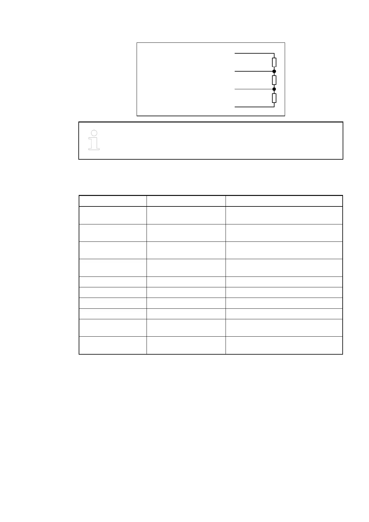
390 Ohms
220 Ohms
390 Ohms
VP (+5 V)
GND (0 V)
RxD/TxD-P
RxD/TxD-N
Data Line B
Data Line A
6
3
8
5
The earthing of the shield should take place at the switch-gear cabinet, see
System-Data AC500
Ä
Chapter 2.6.1 “System Data AC500” on page 1248.
Mounting on terminal units TU517 or TU518:
The assignment of the terminals 1.0 - 1.9:
Terminal Signal Description
1.0 B Data line B (receive and send line, posi-
tive)
1.1 B Data line B (receive and send line, posi-
tive)
1.2 A Data line A (receive and send line, nega-
tive)
1.3 A Data line A (receive and send line, nega-
tive)
1.4 TermB Bus termination data line B
1.5 TermB Bus termination data line B
1.6 TermA Bus termination data line A
1.7 TermA Bus termination data line A
1.8 DGND Reference potential for data transmis-
sion
1.9 DGND Reference potential for data transmis-
sion
At the line ends of a bus segment, termination resistors must be connected. If using TU517/
TU518, the bus termination resistors can be enabled by connecting the terminals TermA and
TermB to the data lines A and B (no external termination resistors are required, see illustration
below).
Communication Interface Modules (S500) > PROFIBUS
2019/04/173ADR010121, 13, en_US984