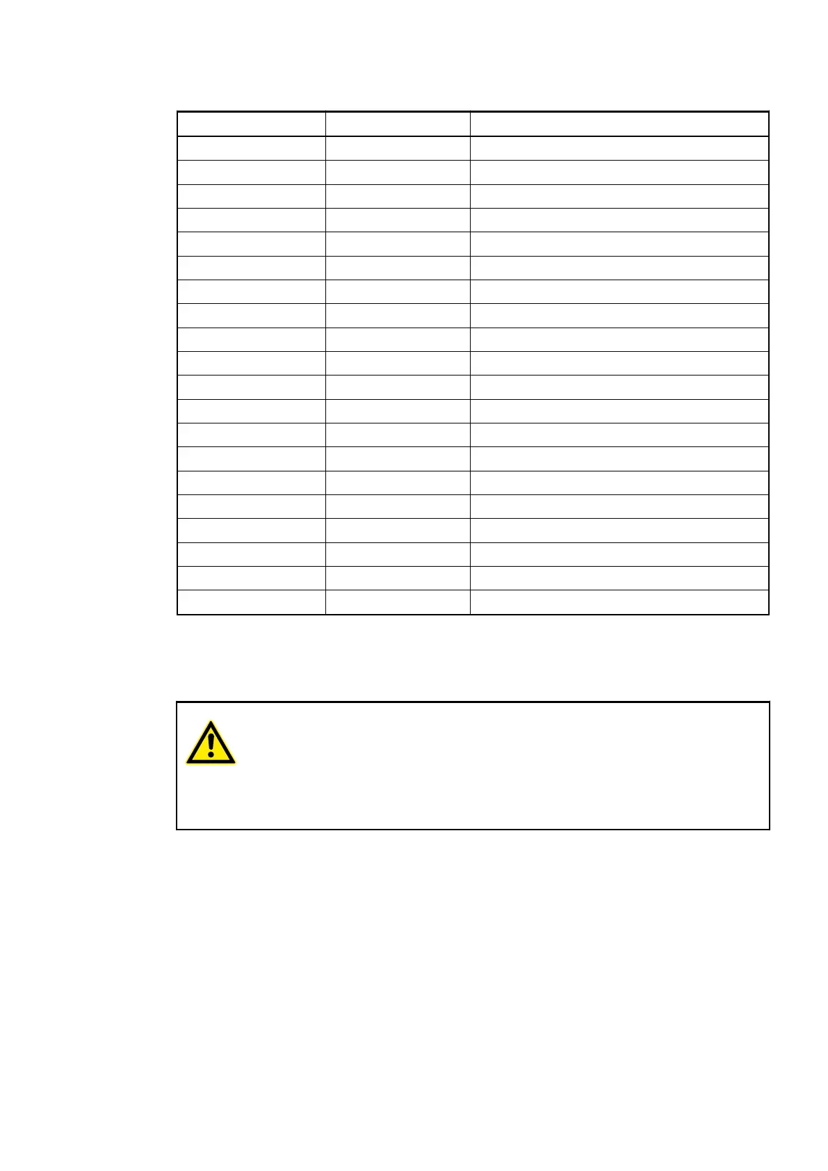
Table 41: Assignment of the Terminals:
Terminal Signal Description
1 I0 Input signal I0
2 N0 Neutral conductor for the input signal I0
3 I1 Input signal I1
4 N1 Neutral conductor for the input signal I1
5 I2 Input signal I2
6 N2 Neutral conductor for the input signal I2
7 I3 Input signal I3
8 N3 Neutral conductor for the input signal I3
9 --- Reserved
10 I4 Input signal I4
11 N4 Neutral conductor for the input signal I4
12 I5 Input signal I5
13 N5 Neutral conductor for the input signal I5
14 I6 Input signal I6
15 N6 Neutral conductor for the input signal I6
16 I7 Input signal I7
17 N7 Neutral conductor for the input signal I7
18 --- Reserved
19 --- Reserved
20 --- Reserved
The internal power supply voltage for the module's circuitry is carried out via the I/O bus (pro-
vided by a bus module or a CPU). Thus, the current consumption from 24 VDC power supply at
the terminals L+/UP and M/ZP of the CPU/bus module increases by 10 mA per DI571.
An external power supply connection is not needed.
WARNING!
Risk of death by electric shock!
The terminals of the module can carry 240 V voltage.
Make sure that all voltage sources (supply and process voltage) are switched
off before you begin with operations at the system.
I/O Modules > Digital I/O Modules
2019/04/17 3ADR010121, 13, en_US 207