Process supply voltage must be connected to UP/ZP of the module. The inputs
and UP/ZP must use the same power supply.
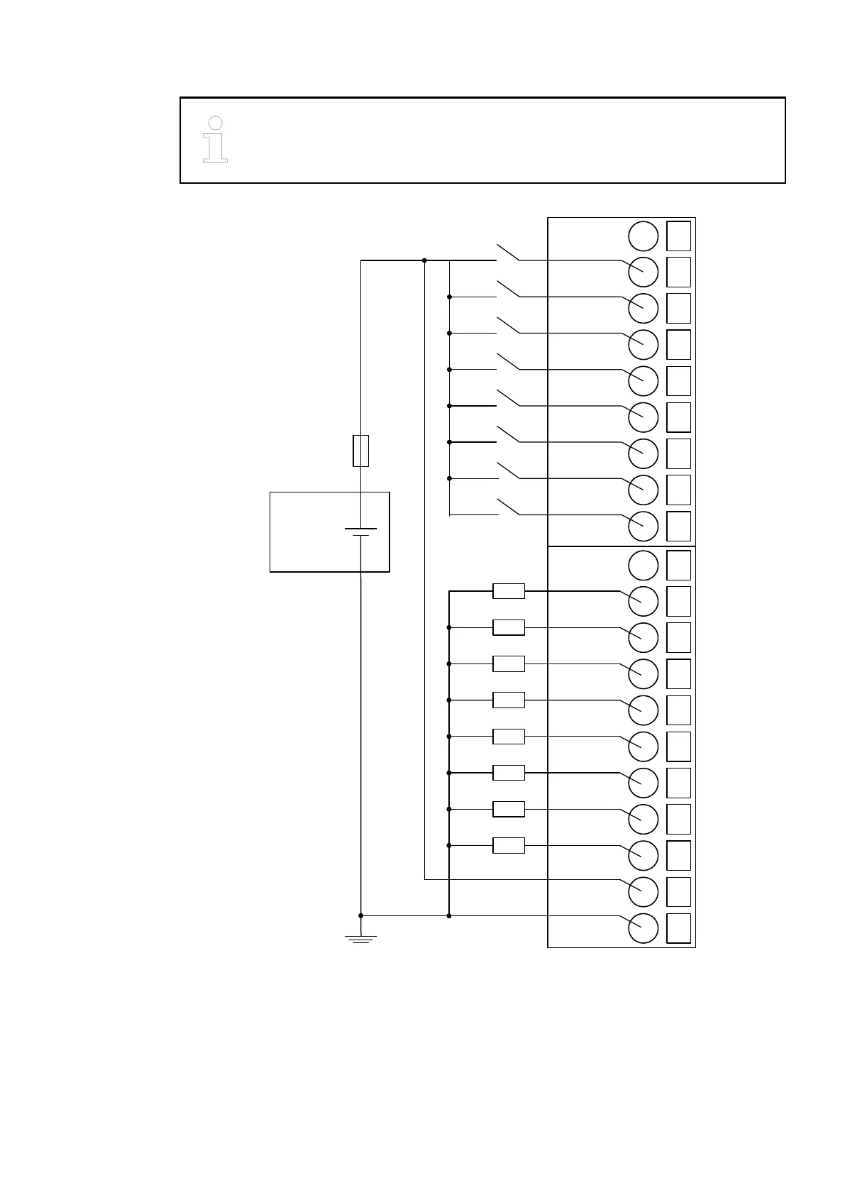
The following figure shows the electrical connection of the digital input/output module DC562:
1
2
--
C0
4
C2
24 VDC
-
+
3
C1
5
C3
6
C4
7
C5
8
C6
9
C7
10
11
---
C8
13
C10
12
C9
14
C11
15
C12
16
C13
17
C14
18
C15
19
UP
20
ZP
In this connection example, the inputs/outputs C0...C7 are connected as inputs and the inputs/
outputs C8...C15 are connected as outputs.
The module provides several diagnosis functions
Ä
Chapter 1.5.1.1.2 “DC562 - Digital Input/
Output Module” on page 179.
The meaning of the LEDs is described in the section State LEDs
Ä
Chapter 1.5.1.1.2.7 “State
LEDs” on page 186.
I/O Modules > Digital I/O Modules
2019/04/173ADR010121, 13, en_US184