AKD User Guide | 10 Configuring General Drive Settings
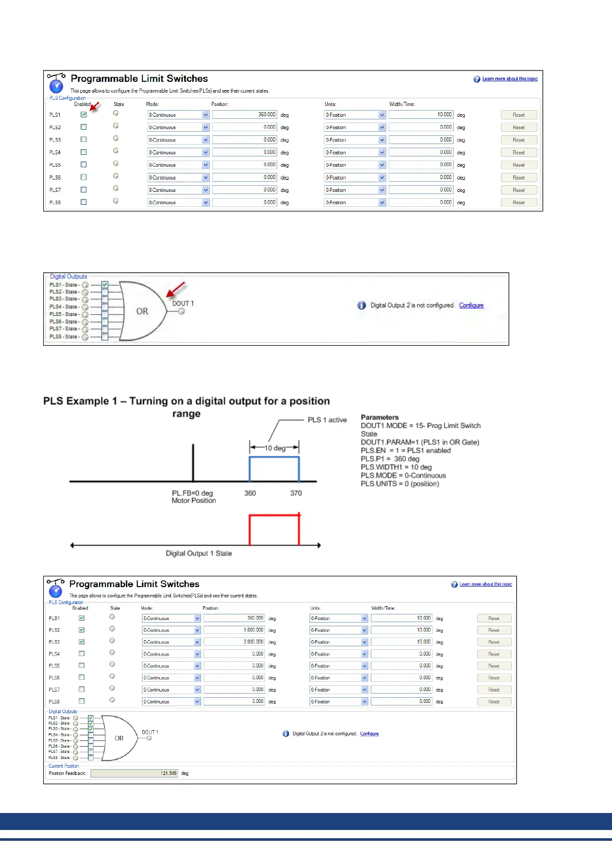
The PLS configuration section of the screen sets the mode and limits of each of the eight PLSs. The PLS is
ignored unless it is enabled (see arrow). In the screen example, PLS1 is set for continuous operation in position
mode. Every time the 360 degree position (PL.FB) is crossed in either direction, the output will turn on for 10
degrees of motor movement.
The final step is to configure the OR gate for the PLSs on which output is triggered. The gate appears for setup in
the screen when a digital output is configured in Mode 15 – Prog Limit Switch State. Since only PLS1 is con-
figured, select PLS 1 (see arrow above)
Tosetup anoutput withmultiple turn-onpoints, configureand enablemore PLS’s and includethem inthe OR Gate.
102 Kollmorgen | December 2010

 Loading...


