2. Closed loop (red): This trace shows the frequency response of G/(1 + G * H) where G = C * P, and H is the
frequency response of anti-resonance filters 3 and 4.
3. Open loop (purple): This trace shows the frequency response of G * H, where G = C * P, and H is the
frequency response of anti-resonance filters 3 and 4.
4. Plant: This trace shows the frequency response of the mechanics of the drive and motor (also referred to
as [P])
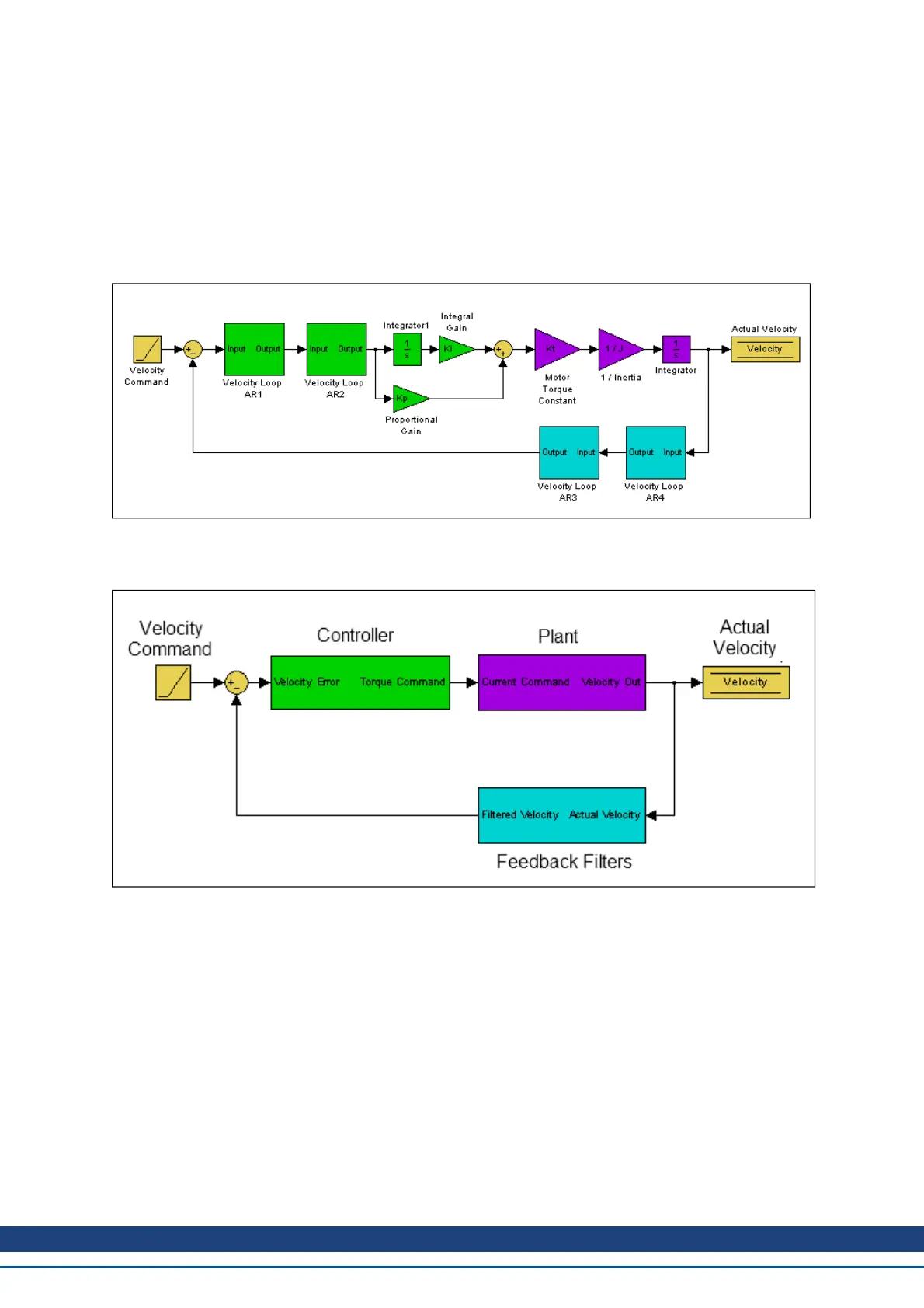
The diagram of the velocity loop on the drive below explains the frequency response that each of these traces rep-
resents:"Tuning Guide" (=> p. 164)
These blocks can be grouped into Controler, Plant, and Feedback sections:
All of the green blocks have been grouped together to create the Controller [C]. The Controller is the portion of the
control loop containing all velocity and position loop tuning, including the forward path filters.
All of the purple blocks have been combined to make the Plant [P]. The plant represents the mechanical and elec-
trical properties of the motor, drive and any mechanical bodies attached to the motor.
The two feedback filters have been combined into one block. This value is never measured directly; however it
contributes to both the Open Loop [G] and Closed Loop [T] frequency responses.
The definition of the Open Loop [G] frequency response is:
Open Loop = Controller x Plant x Feedback Filters
The definition of the Closed Loop [T] frequency response is:
AKD User Guide | 14 Tuning Your System
Kollmorgen | December 2010 161

 Loading...


