Fig. 3-2 1021 – Explanation of the symbols (part 2)
- 1021 -
Function diagram
87654321
fp_1021_51_eng.vsd
DO: All objects
SINAMICS
07.11.13 V04.07.00
Explanations on the function diagrams - Explanation of the symbols (part 2)
Pre-assigned binectors and connectors
Symbols for computational and closed-loop
control functions
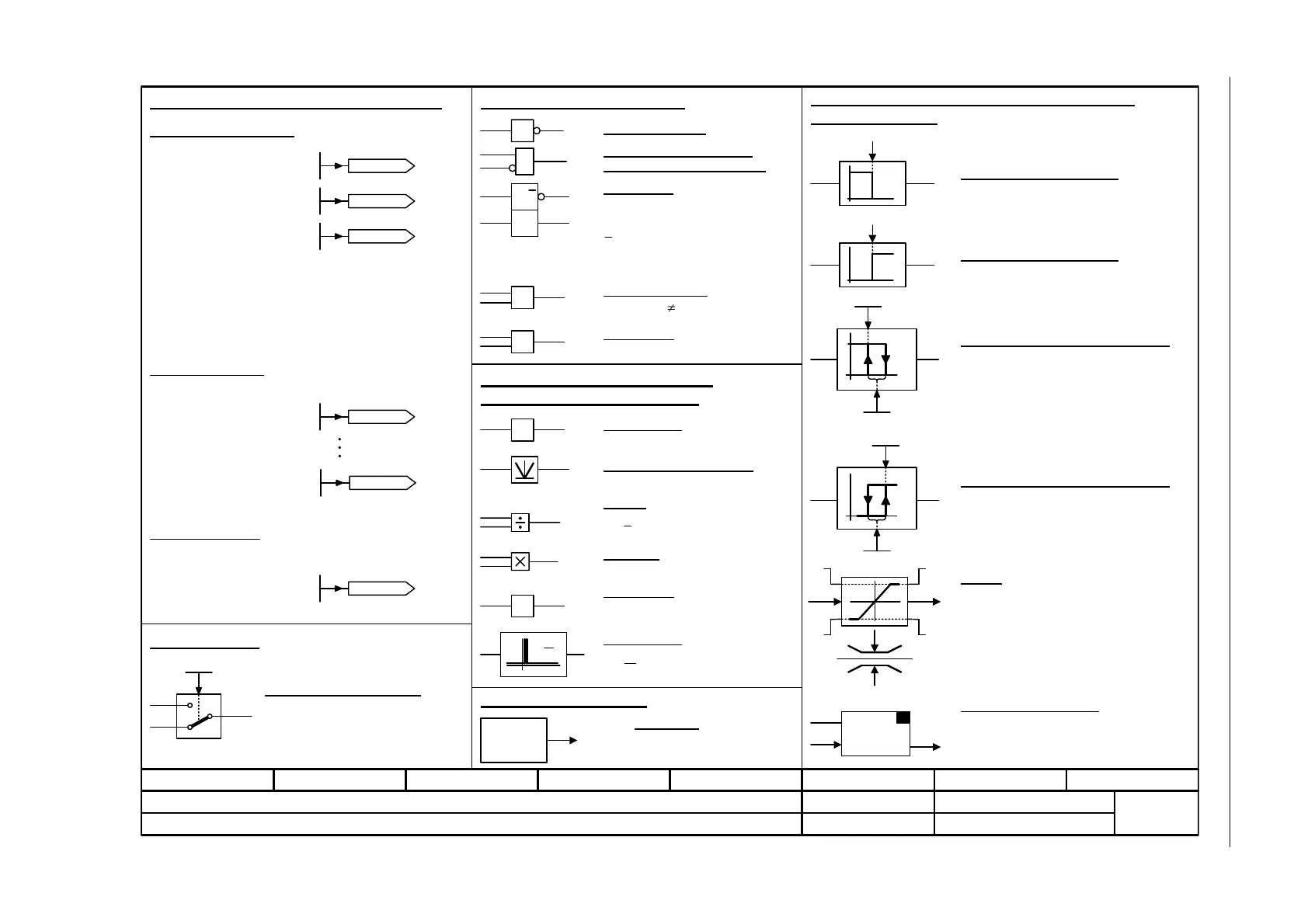
Threshold value switch 1/0
Outputs at y a logical "1" if x < S.
Simple changeover switch
The switch position is shown according to
the factory setting (in this case, switch
position 1 in the default state on delivery).
Limiter
x is limited to the upper limit LU and the lower limit
LL and output at y.
The digital signals MLU and MLL have the value
"1", if the upper or lower limit is active.
p2900[D]
Fixed value 1 [%]
p2901[D]
Fixed value 2 [%]
-10 000.00...10 000.00 [%]
p2900[D] (0.00)
-10 000.00...10 000.00 [%]
p2901[D] (0.00)
Fixed percentage values
S
y
x
1
0
Threshold value switch 0/1
Outputs at y a logical "1" if x > S.
0
1
y
x
S
Sample & Hold element
Sample and hold element.
y = x if SET = 1
(not retentively saved at POWER OFF)
1
0
pxxxx
Fixed speed values
-210 000.000...210 000.000 [1/min]
p1001[D] (0.000)
p1001[D]
n_set_fixed 1
-210 000.000...210 000.000 [1/min]
p1015[D] (0.000)
p1015[D]
n_set_fixed 15
Fixed torque value
-100 000.00...100 000.00 [Nm]
p2930[D] (0.00)
p2930[D]
Fixed value M [Nm]
Switch symbol
Threshold value 1/0 with hysteresis
Outputs a logical "1" at y if x < S.
If x >= S + H then y returns to 0.
0
1
S
H
y
x
Threshold value 0/1 with hysteresis
Outputs a logical "1" at y if x > S.
If x <= S - H then y returns to 0.
0
1
H
S
y
x
r2902[0...14]
Fixed values [%]
p2902[0...14] (0.00)
SET
S & H
xy
Sign reversal
y = -x
Absolute value generator
y = |x|
Divider
y =
Comparator
y = 1 if the analog signal x > 0, i.e. is
positive.
1
&
xy
x
y
>0
-1
xy
x
2
x
1
y
Exclusiv-OR/XOR
y = 1 when x
1
x
2
is.
=1
x
1
y
x
2
Monitoring
Axxxxx
or
Fxxxxx
Symbol for monitoring
Monitoring
In the bottom right-hand corner of
the diagram.
x
1
x
2
Comparator
y = 1 when x
1
= x
2
is.
y
=
x
2
x
1
x
2
x
1
Multiplier
y = x
1
* x
2
AND element with logical
inversion of an input signal
Logical inversion
Symbols for logic functions
R/S flip-flop
S = setting input
R = reset input
Q = non-inverted output
= inverted output
Q
Symbols for computational and
closed-loop control functions
y
R Q
S Q
With a simultaneous 1-signal at the R and
S inputs, the S input dominates.
p2902[0] = +0 %
p2902[1] = +5 %
p2902[2] = +10 %
p2902[3] = +20 %
p2902[4] = +50 %
p2902[5] = +100 %
p2902[6] = +150 %
p2902[7] = +200 %
p2902[8] = -5 %
p2902[9] = -10 %
p2902[10] = -20 %
p2902[11] = -50 %
p2902[12] = -100 %
p2902[13] = -150 %
p2902[14] = -200 %
MLL
MLU
x
y
LU
LL
dx
dt
xy
Y =
dt
dx
Differentiator

 Loading...


