● Module-wise electrically isolated
● Fast counter
● XC version for usage in extreme ambient conditions available
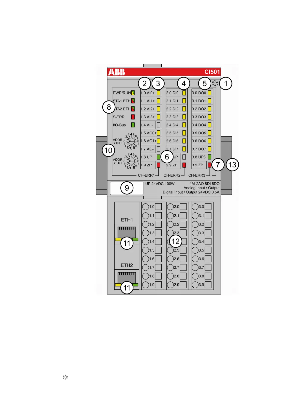
1 I/O bus
2 Allocation between terminal number and signal name
3 6 yellow LEDs to display the signal states of the analog inputs/outputs (AI0 - AI3, AO0 -
AO1)
4 8 yellow LEDs to display the signal states of the digital inputs (DI0 - DI7)
5 8 yellow LEDs to display the signal states of the digital outputs (DO0 - DO7)
6 2 green LEDs to display the process supply voltage UP and UP3
7 3 red LEDs to display errors (CH-ERR1, CH-ERR2, CH-ERR3)
8 5 system LEDs: PWR/RUN, STA1 ETH, STA2 ETH, S-ERR, I/O-Bus
9 Label
10 2 rotary switches for setting the I/O device identifier
11 Ethernet interfaces (ETH1, ETH2) on the terminal unit
12 Terminal unit
13 DIN rail
Sign for XC version
Communication Interface Modules (S500) > PROFINET
2019/04/17 3ADR010121, 13, en_US 1007