For CANopen, only bus cables with characteristics as recommended in ISO 11898 are to be
used. The requirements for the bus cables depend on the length of the bus segment. Regarding
this, the following recommendations are given by ISO 11898:
Length of seg-
ment [m]
Bus cable (shielded, twisted pair) Max. baud rate
[kbit/s]
Conductor
cross section
[mm²]
Line resistance
[W/km]
Wave impe-
dance [W]
0...40 0.25...0.34 /
AWG23, AWG22
70 120 1000 at 40 m
40...300 0.34...0.60 /
AWG22, AWG20
< 60 120 < 500 at 100 m
300...600 0.50...0.60 /
AWG20
< 40 120 < 100 at 500 m
600...1000 0.75...0.80 /
AWG18
< 26 120 < 50 at 1000 m
The ends of the data lines have to be terminated with a 120 W bus terminating resistor. The bus
terminating resistor is usually installed directly at the bus connector.
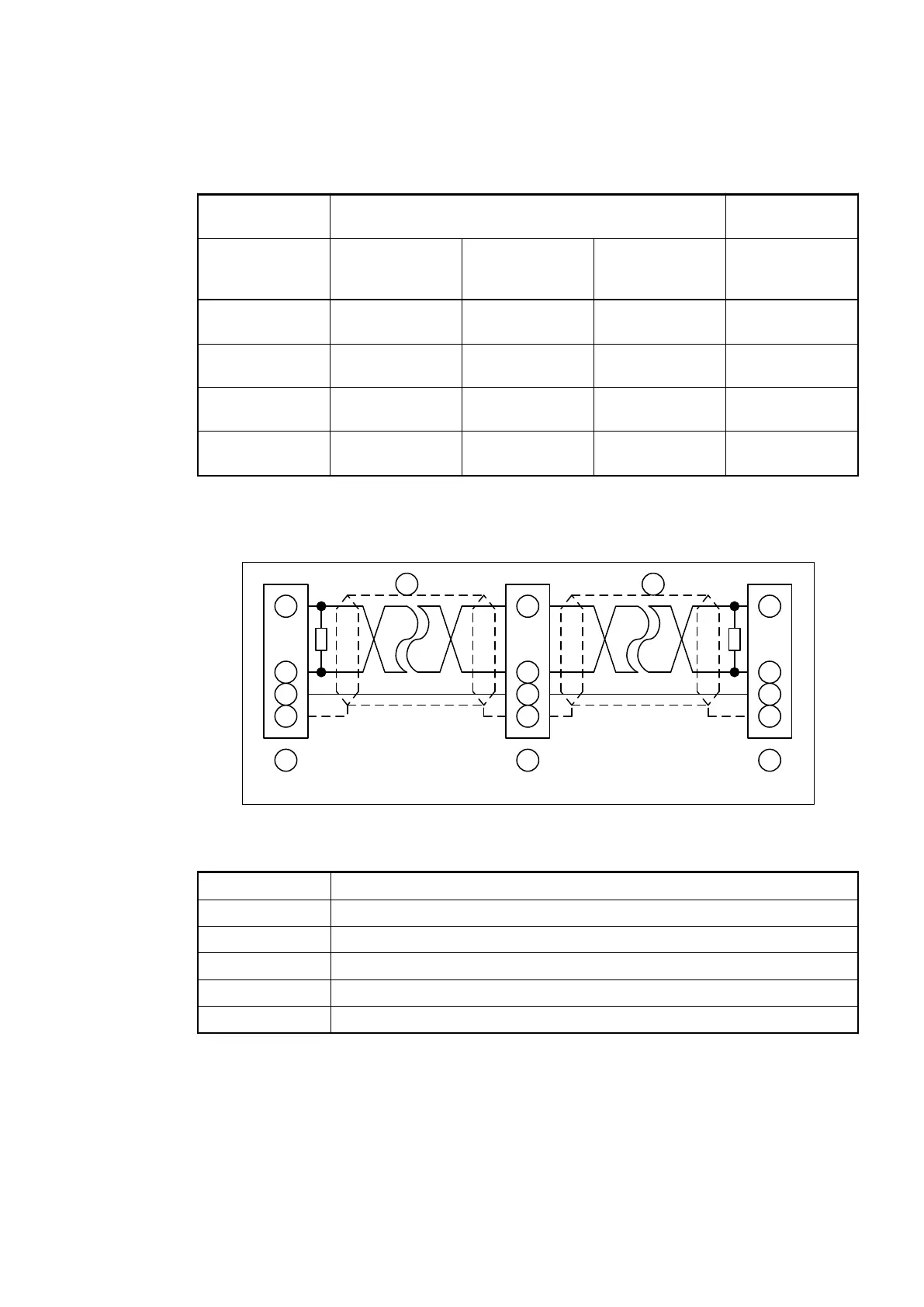
1
2
4
3
1
2
4
3
1
2
4
3
6 6 6
120
120
Node 1 Node 2 Node N
5 5
Fig. 7: CANopen interface, bus terminating resistors connected to the line ends
1 CAN_GND
2 CAN_L
3 Shield
4 CAN_H
5 Data line, shielded twisted pair
6 COMBICON connection, CANopen interface
Types of Bus
Cables
Bus Terminating
Resistors
Communication Modules (AC500 Standard) > CANopen
2019/04/173ADR010121, 13, en_US106