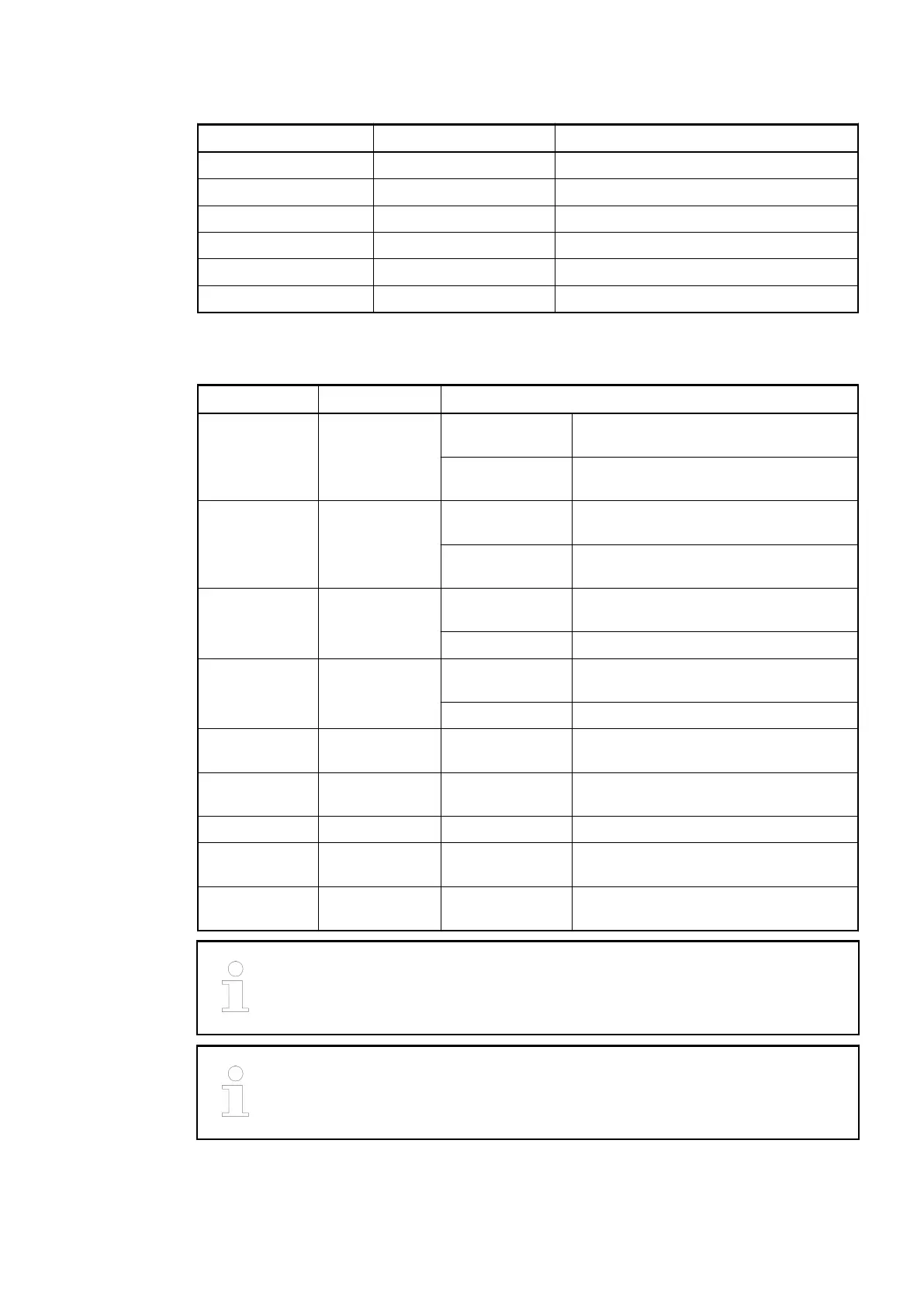
Table 178: Assignment of the terminals
Terminal Signal Description
1.0 UP Process voltage UP (+24 VDC)
1.1 ZP Process voltage ZP (0 VDC)
2.0 UP Process voltage UP (+24 VDC)
2.1 ZP Process voltage ZP (0 VDC)
3.0 UP Process voltage UP (+24 VDC)
3.1 ZP Process voltage ZP (0 VDC)
Table 179: Assignment of the terminals of removable connectors X11, X12 and X13 (Serial inter-
faces)
Terminal Signal Description
1 Term-P RS-485 Internal line terminating resistor for non-
inverted signal (Rx/Tx-P)
RS-422 Non-inverted receive signal terminal
(RxD+)
2 Rx/Tx-P RS-485 Non-inverted I/O signal terminal for
each channel
RS-422 Non-inverted transmit signal terminal
(TxD+)
3 Rx/Tx-N RS-485 Inverted I/O signal terminal for each
channel
RS-422 Inverted transmit signal terminal (TxD-)
4 Term-N RS-485 Internal line-terminating-resistor for
inverted signal (Rx/Tx-N) terminal
RS-422 Inverted receive signal terminal (RxD-)
5 RTS RS-232 Request To Send signal terminal for
each channel
6 TxD RS-232 Transmit signal terminal for each
channel
7 SGND RS-232 Signal ground for each channel
8 RxD RS-232 Receive signal terminal for each
channel
9 CTS RS-232 Clear To Send signal terminal for each
channel
The connection of SGND (ground) is optional for RS-485/RS-422.
For RS-422, no external line-terminating resistors have to connected. They are
already connected inside the module.
Communication Interface Modules (S500) > PROFINET
2019/04/173ADR010121, 13, en_US1072