ETH1
ETH2
5
1
2
3
4
6
7
8
9
5
1
2
3
4
6
7
8
9
5
1
2
3
4
6
7
8
9
X11 X12 X13
1.0
1.1
3.0
3.1
2.0
2.1
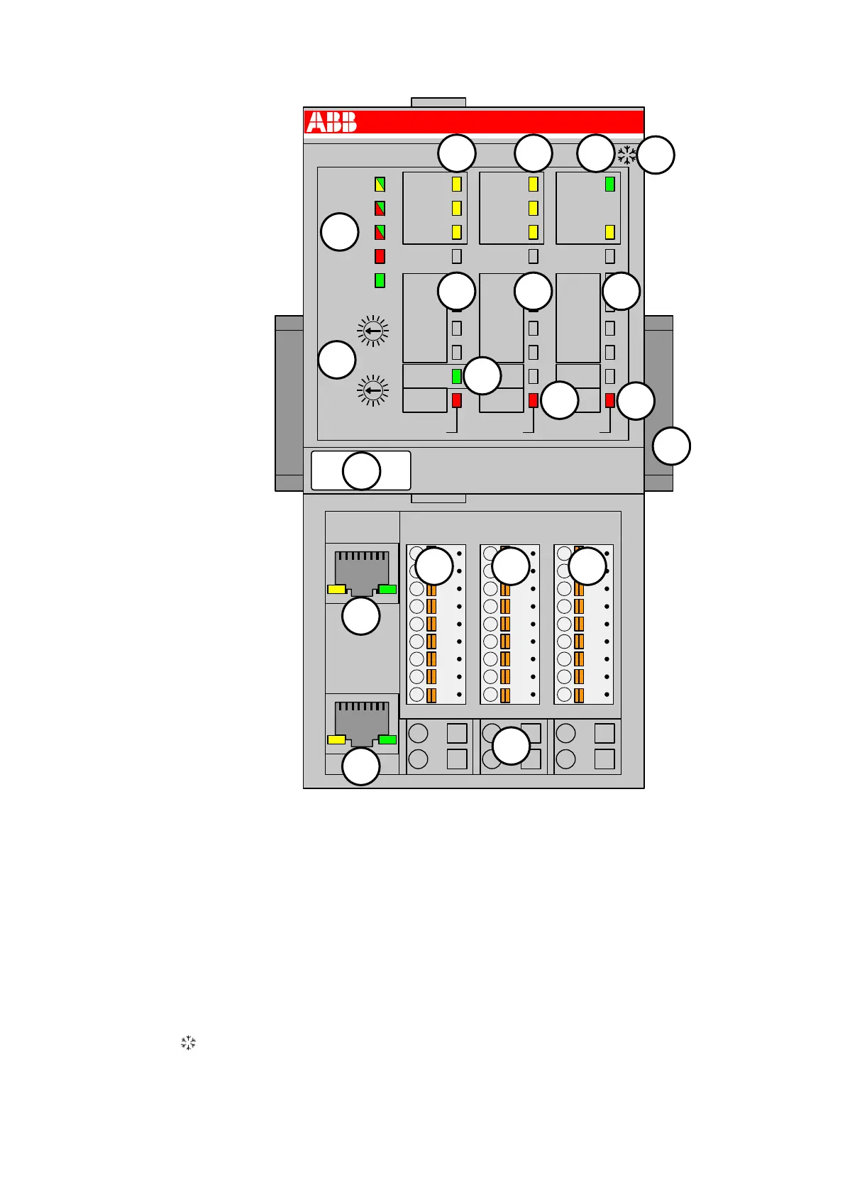
CI506
UP 24VDC 5W
PROFINET IO Device
2x Serial Interface (RS232/485/422)
STA1 ETH
PWR/RUN
STA2 ETH
S-ERR
COM1-ERR
I/O-Bus
1.1
ZP
1.0
UP
COM1
TxD
COM1
RxD
COM1
STA
X11 - COM1
1 Term-P
2 Rx/Tx-P
3 Rx/Tx-N
4 Term-N
5 RTS
6 TxD
7 SGND
8 RxD
9 CTS
Proxy to CAN2 0A / CANopen Master
CAN-ERR
3.1
ZP
CAN
TxD
CAN
STA
X13 - CAN
1 Term+
2 CAN+
3 CAN-
4 Term-
7 CAN_GND
3.0
UP
COM2-ERR
2.1
ZP
COM2
TxD
COM2
RxD
COM2
STA
X12 - COM2
1 Term-P
2 Rx/Tx-P
3 Rx/Tx-N
4 Term-N
5 RTS
6 TxD
7 SGND
8 RxD
9 CTS
2.0
UP
ADDR
x01H
4
C
3
B
2
A
1
9
0
8
F
7
E
6
D
5
x10H
ADDR
4
C
3
B
2
A
1
9
0
8
F
7
E
6
D
5
1
2 2
12
13
14
15
3
4
5 5
6
7
8
9
10
11
12
1313
1 I/O bus
2 2 x 3 yellow LEDs to display the signal states of the serial interfaces COM1 and COM2
3 1 green and 1 yellow LEDs to display the signal states of the CANopen interface
4 5 system LEDs: PWR/RUN, STA1 ETH, STA2 ETH, S-ERR, I/O-Bus
5 Allocation between terminal number and signal name of the serial interfaces
6 Allocation between terminal number and signal name of the CANopen interface
7 2 rotary switches for setting the IO device identifier
8 1 green LED to display the process voltage UP
9 2 red LEDs to display errors (COM1-ERR, COM2-ERR) of the serial interfaces
10 1 red LED to display errors (CAN-ERR) of the CANopen interface
11 Label
12 Ethernet Interfaces (ETH1, ETH2) on the terminal unit
13 3 removable connectors to connect the subordinated interfaces
14 6 spring terminals for power supply voltage (UP)
15 DIN rail
Sign for XC version
Communication Interface Modules (S500) > PROFINET
2019/04/17 3ADR010121, 13, en_US 1085