120
120
4
2
3
1
4
2
3
1
+24 V
0 V
5
6
7
9
11
5
7
12
13
8
10
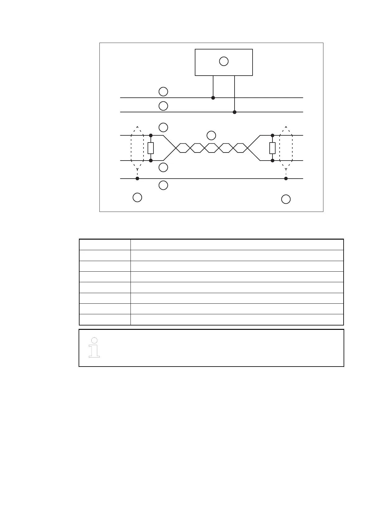
Fig. 10: DeviceNet interface, bus terminating resistors connected to the line ends
6 DeviceNet power supply
7 COMBICON connection, DeviceNet interface
8 Data lines, twisted pair cables
9 red
10 black
11 white
12 blue
13 bare
The earthing of the shield should take place at the switch-gear. Please refer to
Ä
Chapter 2.6.1 “System Data AC500” on page 1248.
Communication Modules (AC500 Standard) > CANopen
2019/04/17 3ADR010121, 13, en_US 113