Length of seg-
ment [m]
Bus cable (shielded, twisted pair) Max. baud rate
[kbit/s]
Conductor
cross section
[mm²]
Line resistance
[W/km]
Wave impe-
dance [W]
0...40 0.25...0.34 /
AWG23, AWG22
70 120 1000 at 40 m
40...300 0.34...0.60 /
AWG22, AWG20
< 60 120 < 500 at 100 m
300...600 0.50...0.60 /
AWG20
< 40 120 < 100 at 500 m
600...1000 0.75...0.80 /
AWG18
< 26 120 < 50 at 1000 m
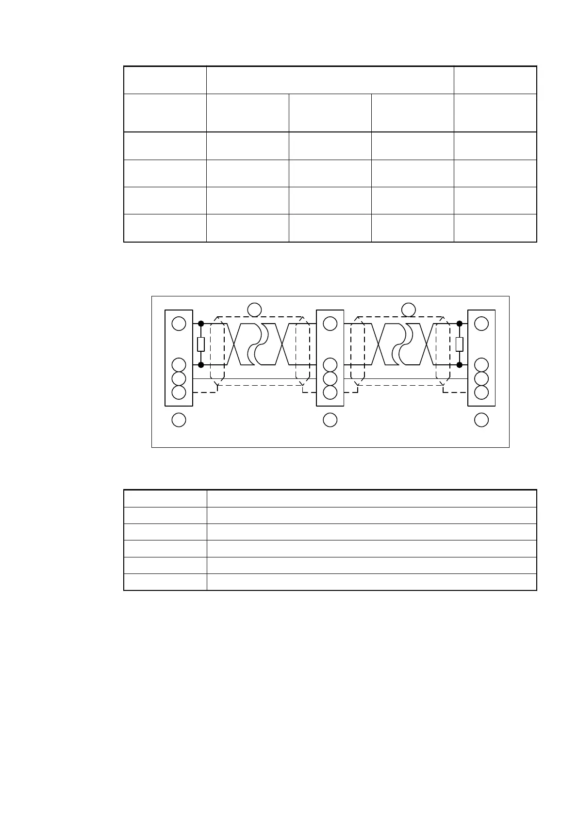
The ends of the data lines have to be terminated with a 120 W bus terminating resistor. The bus
terminating resistor is usually installed directly at the bus connector.
1
2
4
3
1
2
4
3
1
2
4
3
6 6 6
120
120
Node 1 Node 2 Node N
5 5
Fig. 9: CANopen interface, bus terminating resistors connected to the line ends
1 CAN_GND
2 CAN_L
3 Shield
4 CAN_H
5 Data line, shielded twisted pair
6 COMBICON connection, CANopen interface
Bus Terminating
Resistors
Communication Modules (AC500 Standard) > CANopen
2019/04/173ADR010121, 13, en_US112