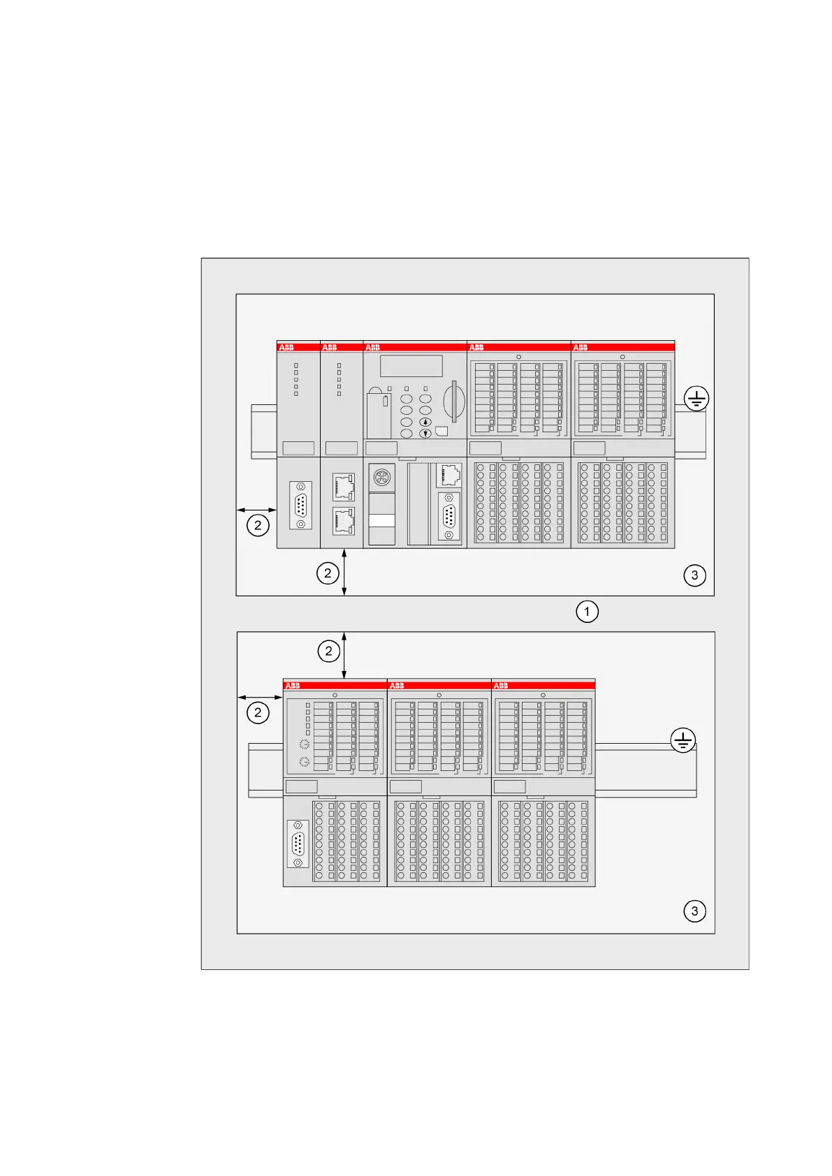
Maintain spacing from:
● enclosure walls
● wireways
● adjacent equipment
Allow a minimum of 20 mm clearance on all sides. This provides ventilation and electrical isola-
tion.
It is recommended to mount the modules on an earthed mounting plate, or an earthed DIN rail,
independent of the mounting location.
Fig. 201: Installation of AC500/S500 modules in a switch-gear cabinet
1 Cable duct
2 Distance from cable duct ≥20 mm
3 Mounting plate, earthed
System Assembly, Construction and Connection
AC500-eCo > Mechanical Dimensions
2019/04/17 3ADR010121, 13, en_US 1197