1
2
I0
N0
4
N1
3
I1
5
I2
6
N2
7
I3
8
N3
9
−−−
10
11
I4
N4
13
N5
12
I5
14
I6
15
N6
16
I7
17
N7
18
−−−
19
−−−
20
−−−
L
N
L
N
L
N
L
N
L
N
L
N
L
N
L
N
L0
N0
L7
N7
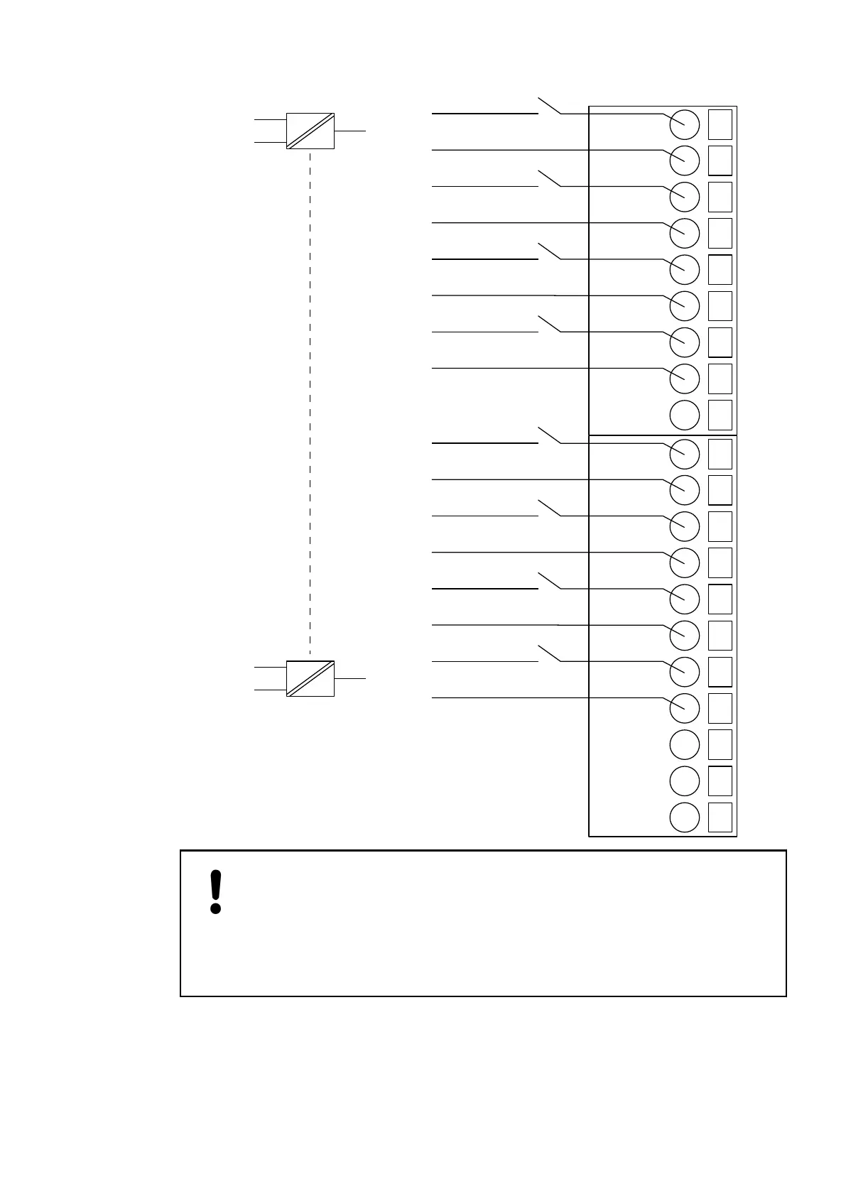
NOTICE!
Risk of damaging the PLC modules!
The PLC modules will be irreparably damaged if a voltage > 240 V is con-
nected.
Make sure that all inputs are fed from the same phase. The module must not be
connected to a 400 V voltage.
The module provides several diagnosis functions
Ä
Chapter 1.5.1.1.5.7 “Diagnosis”
on page 211.
The meaning of the LEDs is described in the section State LEDs
Ä
Chapter 1.5.1.1.5.8 “State
LEDs” on page 211.
I/O Modules > Digital I/O Modules
2019/04/17 3ADR010121, 13, en_US 209