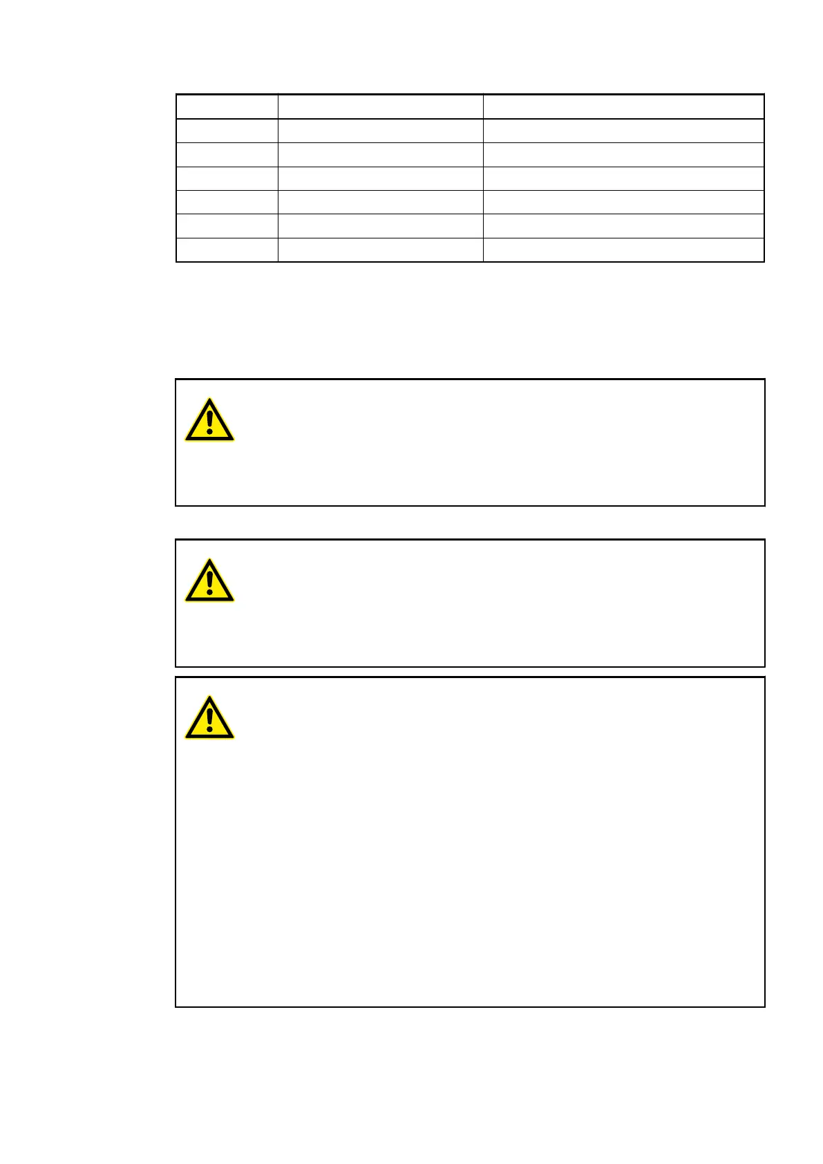
Terminal Signal Description
15 NO13 Normally-open contact of the output NO13
16 NO14 Normally-open contact of the output NO14
17 NO15 Normally-open contact of the output NO15
18 R8..15 Output common for signals NO8 to NO15
19 L+ Process voltage L+ (24 VDC)
20 M Process voltage M (0 VDC)
The internal power supply voltage for the module's circuitry is carried out via the I/O bus (pro-
vided by a bus module or a CPU). Thus, the current consumption from 24 VDC power supply at
the terminals L+/UP and M/ZP of the CPU/bus module increases by 5 mA per DO573.
The external power supply connection is carried out via the L+ (+24 VDC) and the M (0 VDC)
terminals. The M terminal is electrically interconnected to the M/ZP terminal of the CPU/bus
module.
WARNING!
Risk of death by electric shock!
The terminals of the module can carry 240 V voltage.
Make sure that all voltage sources (supply and process voltage) are switched
off before you begin with operations at the system.
For screw-type terminals only:
WARNING!
For screw terminals only: Danger of death by electric shock!
The IP 20 protection degree is only provided if all terminal screws are tightened.
Tighten all screws of unused load terminals of relay outputs if voltages > 24 V
are connected to the relay group.
WARNING!
Removal/Insertion under power
The devices are not designed for removal or insertion under power. Because of
unforeseeable consequences, it is not allowed to plug or unplug devices with
the power being ON.
Make sure that all voltage sources (supply and process voltage) are switched
off before you
– connect or disconnect any signal or terminal block
– remove, mount or replace a module.
Disconnecting any powered devices while energized in a hazardous location
could result in an electric arc, which could create a flammable ignition resulting
in fire or explosion.
Make sure that power is removed and that the area has been thoroughly
checked to ensure that flammable materials are not present prior to proceeding.
The devices must not be opened when in operation. The same applies to the
network interfaces.
I/O Modules > Digital I/O Modules
2019/04/17 3ADR010121, 13, en_US 263