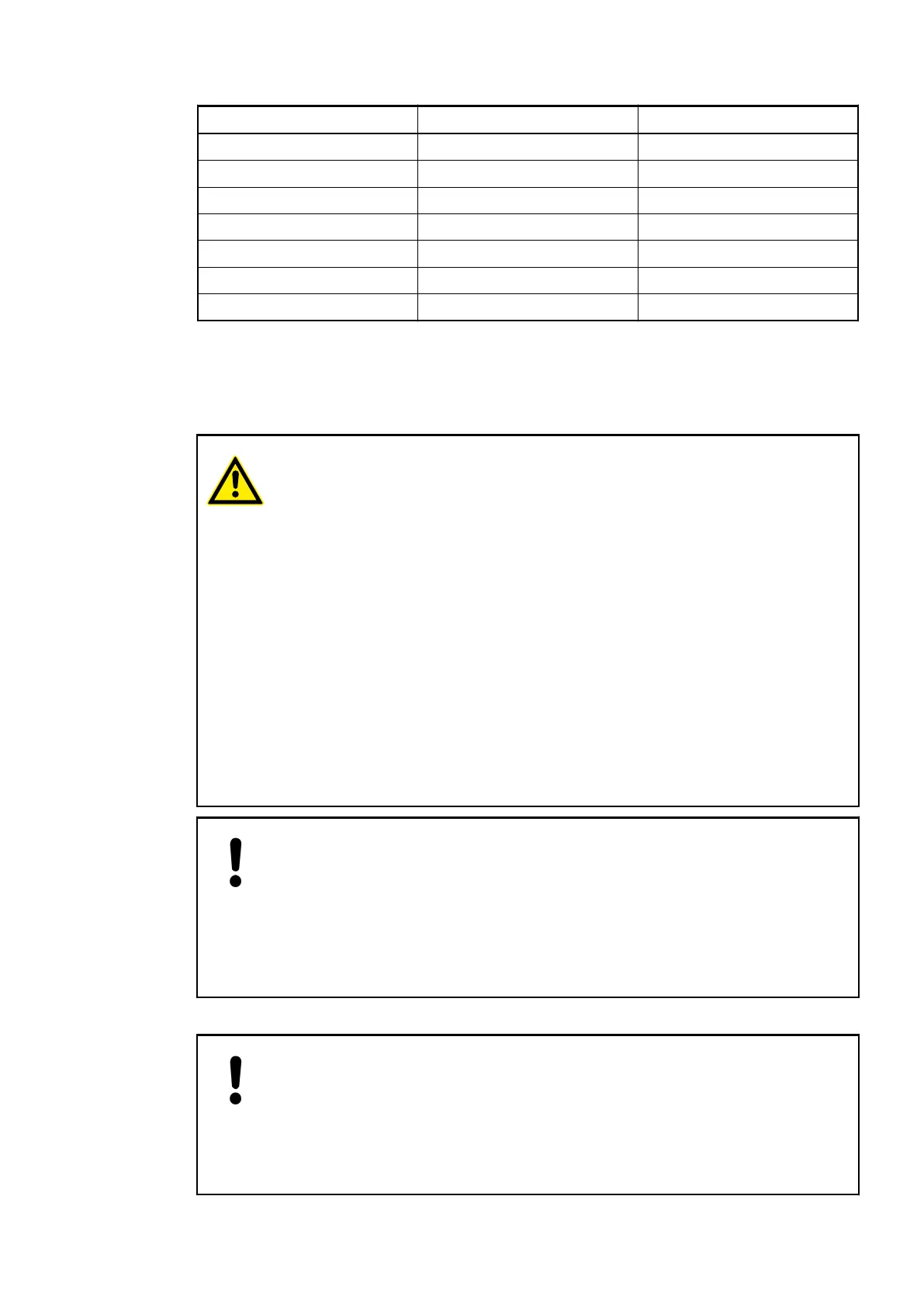
Terminal Signal Description
14 O3 Output signal O3
15 O4 Output signal O4
16 O5 Output signal O5
17 O6 Output signal O6
18 O7 Output signal O7
19 UP Process voltage UP +24 VDC
20 ZP Process voltage ZP 0 VDC
The internal power supply voltage for the module's circuitry is carried out via the I/O bus (pro-
vided by a bus module or a CPU). Thus, the current consumption from 24 VDC power supply at
the terminals L+/UP and M/ZP of the CPU/bus module increases by 10 mA per DX561.
The external power supply connection is carried out via the UP (+24 VDC) and ZP (0 VDC) ter-
minals.
WARNING!
Removal/Insertion under power
The devices are not designed for removal or insertion under power. Because of
unforeseeable consequences, it is not allowed to plug or unplug devices with
the power being ON.
Make sure that all voltage sources (supply and process voltage) are switched
off before you
– connect or disconnect any signal or terminal block
– remove, mount or replace a module.
Disconnecting any powered devices while energized in a hazardous location
could result in an electric arc, which could create a flammable ignition resulting
in fire or explosion.
Make sure that power is removed and that the area has been thoroughly
checked to ensure that flammable materials are not present prior to proceeding.
The devices must not be opened when in operation. The same applies to the
network interfaces.
NOTICE!
Risk of damaging the PLC modules!
Overvoltages and short circuits might damage the PLC modules.
– Make sure that all voltage sources (supply and process voltage) are
switched off before you begin with operations at the system.
– Never connect any voltages or signals to reserved terminals (marked with
---). Reserved terminals may carry internal voltages.
The digital inputs can be used as source inputs or as sink inputs.
NOTICE!
Risk of malfunctions in the plant!
A ground closure, e. g. caused by a damaged cable insulation, can bridge
switches accidentally.
Use sink inputs when possible or make sure that, in case of error, there will be
no risks to persons or plant.
I/O Modules > Digital I/O Modules
2019/04/173ADR010121, 13, en_US276