Fig. 31: Internal construction
The internal power supply voltage for the module's circuitry is carried out via the I/O bus (pro-
vided by a bus module or a CPU). Thus, the current consumption from 24 VDC power supply at
the terminals L+/UP and M/ZP of the CPU/bus module increases by 2 mA per DX531. The
external power supply connection is carried out via the UP (+24 VDC) and the ZP (0 VDC) ter-
minals.
NOTICE!
Risk of damaging the PLC modules!
Overvoltages and short circuits might damage the PLC modules.
– Make sure that all voltage sources (supply and process voltage) are
switched off before you begin with operations at the system.
– Never connect any voltages or signals to reserved terminals (marked with
---). Reserved terminals may carry internal voltages.
WARNING!
Risk of death by electric shock!
The terminals of the module can carry 240 V voltage.
Make sure that all voltage sources (supply and process voltage) are switched
off before you begin with operations at the system.
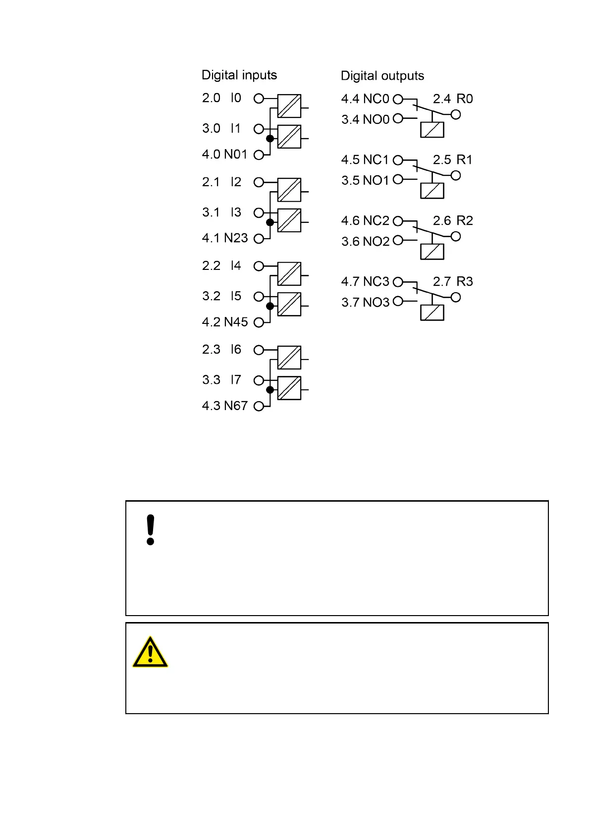
The following figure shows the electrical connection of the module:
I/O Modules > Digital I/O Modules
2019/04/173ADR010121, 13, en_US386