I0+ 2
I0− 3
R0 1
+
−
I1+ 5
I1− 6
R1 4
+
−
I2+ 8
I2− 9
R2 7
+
−
I3+ 11
I3− 12
R3 10
+
−
O0U+ 13
O0I+ 14
O1I+ 16
O01− 17
O1U+ 15
L+ 19
M 20
SG 18
+
+
−
−
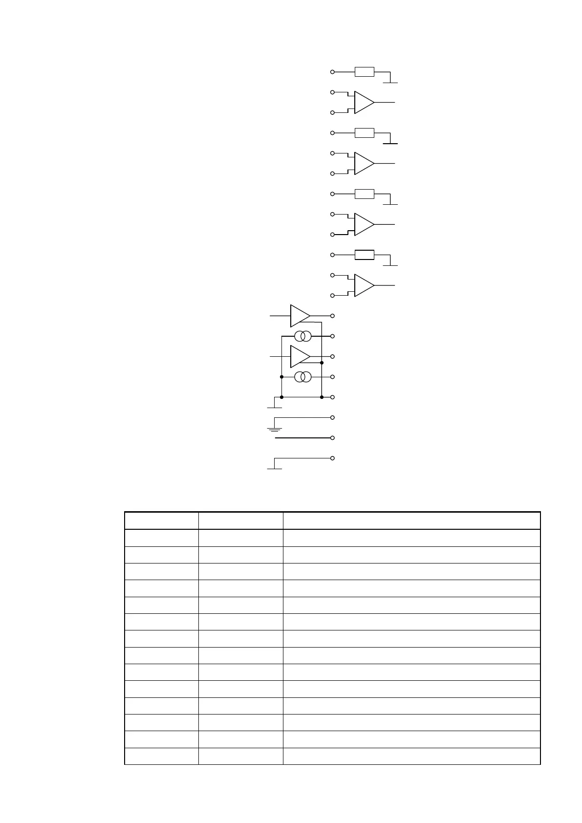
The assignment of the terminals:
Terminal Signal Description
1 R0 Burden resistor for input signal 0 for current sensing
2 I0+ Positive pole of input signal 0
3 I0- Negative pole of input signal 0
4 R1 Burden resistor for input signal 1 for current sensing
5 I1+ Positive pole of input signal 1
6 I1- Negative pole of input signal 1
7 R2 Burden resistor for input signal 2 for current sensing
8 I2+ Positive pole of input signal 2
9 I2- Negative pole of input signal 2
10 R3 Burden resistor for input signal 3 for current sensing
11 I3+ Positive pole of input signal 3
12 I3- Negative pole of input signal 3
13 O0U+ Voltage output of channel 0
14 O0I+ Current output of channel 0
I/O Modules > Analog I/O Modules
2019/04/173ADR010121, 13, en_US440