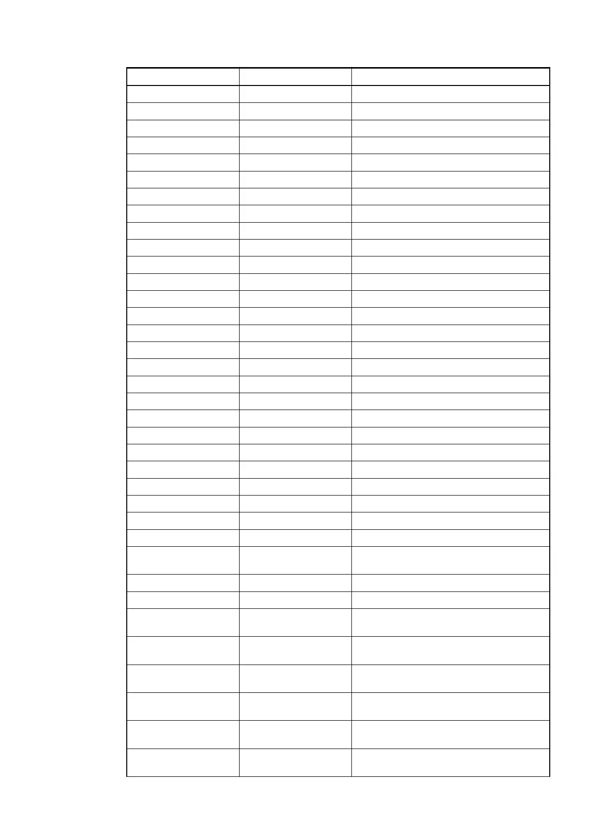
Terminal Signal Description
1.0 DI0 Signal of the digital input DI0
1.1 DI1 Signal of the digital input DI1
1.2 DI2 Signal of the digital input DI2
1.3 DI3 Signal of the digital input DI3
1.4 DI4 Signal of the digital input DI4
1.5 DI5 Signal of the digital input DI5
1.6 DI6 Signal of the digital input DI6
1.7 DI7 Signal of the digital input DI7
1.8 UP Process voltage UP (24 VDC)
1.9 ZP Process voltage ZP (0 VDC)
2.0 DI8 Signal of the digital input DI8
2.1 DI9 Signal of the digital input DI9
2.2 DI10 Signal of the digital input DI10
2.3 DI11 Signal of the digital input DI11
2.4 DI12 Signal of the digital input DI12
2.5 DI13 Signal of the digital input DI13
2.6 DI14 Signal of the digital input DI14
2.7 DI15 Signal of the digital input DI15
2.8 UP Process voltage UP (24 VDC)
2.9 ZP Process voltage ZP (0 VDC)
3.0 AI0+ Positive pole of analog input signal 0
3.1 AI1+ Positive pole of analog input signal 1
3.2 AI2+ Positive pole of analog input signal 2
3.3 AI3+ Positive pole of analog input signal 3
3.4 AI- Negative pole of analog input signals 0 to 3
3.5 AO0+ Positive pole of analog output signal 0
3.6 AO1+ Positive pole of analog output signal 1
3.7 AO- Negative pole of analog output signals 0
and 1
3.8 UP Process voltage UP (24 VDC)
3.9 ZP Process voltage ZP (0 VDC)
4.0 C16 Signal of the configurable digital input/
output C16
4.1 C17 Signal of the configurable digital input/
output C17
4.2 C18 Signal of the configurable digital input/
output C18
4.3 C19 Signal of the configurable digital input/
output C19
4.4 C20 Signal of the configurable digital input/
output C20
4.5 C21 Signal of the configurable digital input/
output C21
I/O Modules > Digital/Analog I/O Modules
2019/04/17 3ADR010121, 13, en_US 571