NOTICE!
Risk of damaging the PLC modules!
Overvoltages and short circuits might damage the PLC modules.
– Make sure that all voltage sources (supply and process voltage) are
switched off before you begin with operations at the system.
– Never connect any voltages or signals to reserved terminals (marked with
---). Reserved terminals may carry internal voltages.
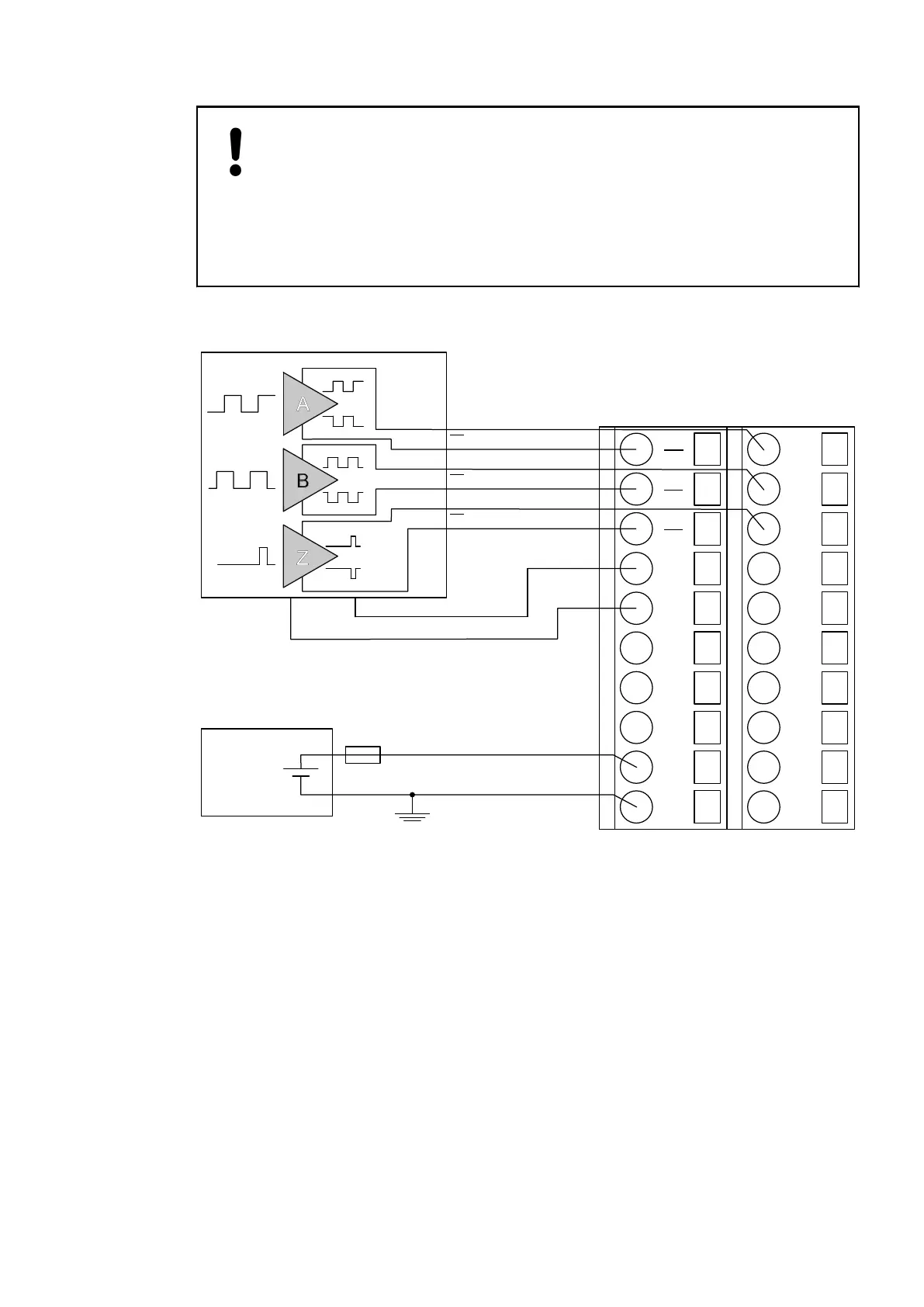
The encoder is powered by the 5 V power supply which is integrated in CD522.
1.0
A0
1.1
B0
1.2
Z0
1.3
5V0
1.4
0V
1.5
O0
1.6
0V
1.7
O1
1.8
UP
1.9
ZP
2.0
A0
2.1
B0
2.2
Z0
2.3
I3
2.4
C4
2.5
C5
2.6
C6
2.7
C7
2.8
UP
2.9
ZP
24 V DC
−
+
A
B
Z
5 V DC
+
−
A
A
B
B
Z
Z
The encoder is powered by the 5 V power supply which is integrated in the CD522.
Connection of
Encoders with
Differential
RS-422 Signal
Connection of
Encoders with 5
V TTL Signal
2019/04/173ADR010121, 13, en_US656