Parameter Value
Output voltage for signal 1 L+ (-0.8 V)
Output delay (0->1 or 1->0) On request
Output current
Rated value, per channel: 500 mA at UP =
24 V
500 mA at L+ = 24 V
Maximum value: 1 A 1 A
Leakage current with signal 0 < 0.5 mA
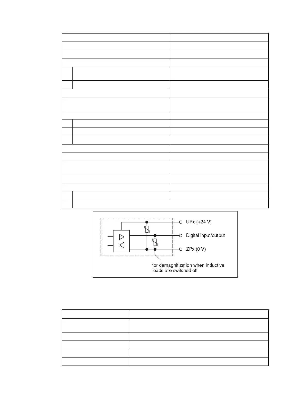
Demagnetization when inductive loads are
switched off
With varistors integrated in the module
Switching frequency
With resistive load On request
With inductive loads Max. 0.5 Hz
With lamp loads Max. 11 Hz with max. 5 W
Short-circuit proof / overload proof Yes
Overload message (I > 0.7 A) Yes, after ca. 100 ms
Output current limitation Yes, automatic reactivation after short cir-
cuit/overload
Resistance to feedback against 24 V signals Yes
Max. cable length
Shielded 1000 m
Unshielded 600 m
Fig. 113: Circuitry of a digital input/output with the varistors for demagnetization when inductive
loads are switched off.
Table 105: Technical Data of High Speed Input (Encoder, A/B/Z)
Parameter Value
Number of channels per
module
3 (sampled synchronously with IEPE inputs)
Connection Terminals 1.1, 1.2, 1.3, 1.4, 1.5, 1.6
Reference potential Terminals 1.9, 4.9, 5.9, 6.9, 7.9 for M (0 V)
Indication of the input signals One LED per channel
Resolution 32 bits
2019/04/173ADR010121, 13, en_US694