6 --- Reserved
7 CAN+ Non-inverted signal of the CAN Bus
8 --- Reserved
9 --- Reserved
Shield Cable shield Functional earth
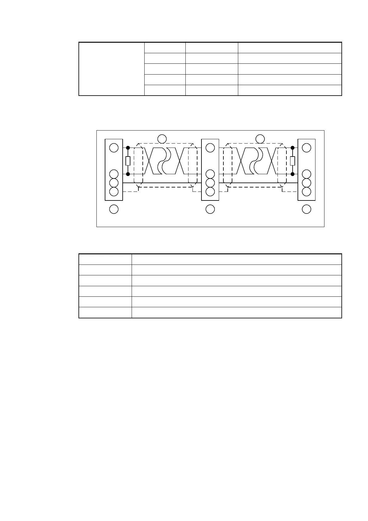
The ends of the data lines have to be terminated with a 120 W bus terminating resistor. The bus
terminating resistor is usually installed directly at the bus connector.
1
2
4
3
1
2
4
3
1
2
4
3
6 6 6
120
120
Node 1 Node 2 Node N
5 5
Fig. 114: CANopen interface, bus terminating resistors connected to the line ends
1 CAN_GND
2 CAN_L
3 Shield
4 CAN_H
5 Data line, shielded twisted pair
6 COMBICON connection, CANopen interface
Bus Terminating
Resistors
Communication Interface Modules (S500) > CANopen
2019/04/17 3ADR010121, 13, en_US 705