120
120
4
2
3
1
4
2
3
1
+24 V
0 V
5
6
7
9
11
5
7
12
13
8
10
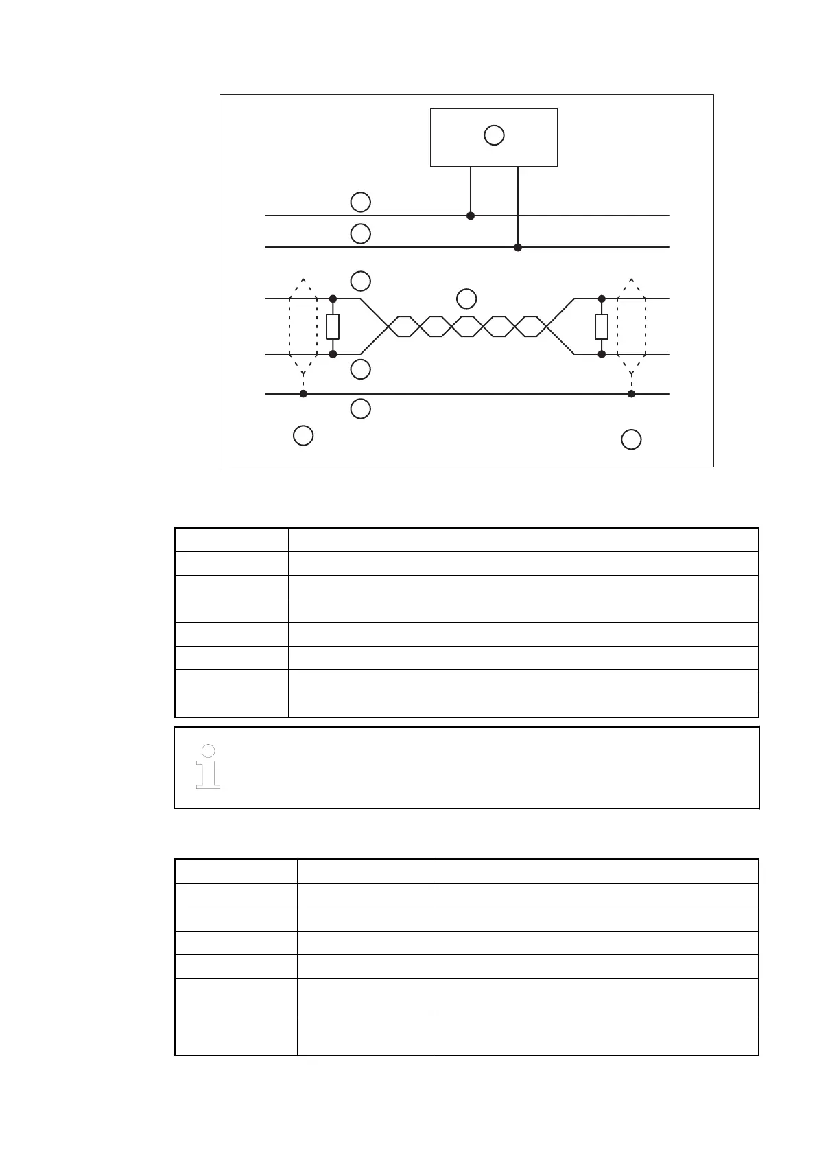
Fig. 115: DeviceNet interface, bus terminating resistors connected to the line ends
6 DeviceNet power supply
7 COMBICON connection, DeviceNet interface
8 Data lines, twisted pair cables
9 red
10 black
11 white
12 blue
13 bare
The earthing of the shield should take place at the switch-gear. Please refer to
Ä
Chapter 2.6.1 “System Data AC500” on page 1248.
Table 109: Assignment of the terminals
Terminal Signal Description
1.0 CAN+ Non-inverted signal of the CAN Bus
1.1 CAN+ Non-inverted signal of the CAN Bus
1.2 CAN- Inverted signal of the CAN Bus
1.3 CAN- Inverted signal of the CAN Bus
1.4 Term+ CAN bus termination for CAN+ (for bus termination,
Term+ must be connected with CAN+)
1.5 Term+ CAN bus termination for CAN+ (connecting alterna-
tive for terminal 1.4)
Mounting on
Terminal Units
TU517 or TU518
Communication Interface Modules (S500) > CANopen
2019/04/173ADR010121, 13, en_US706