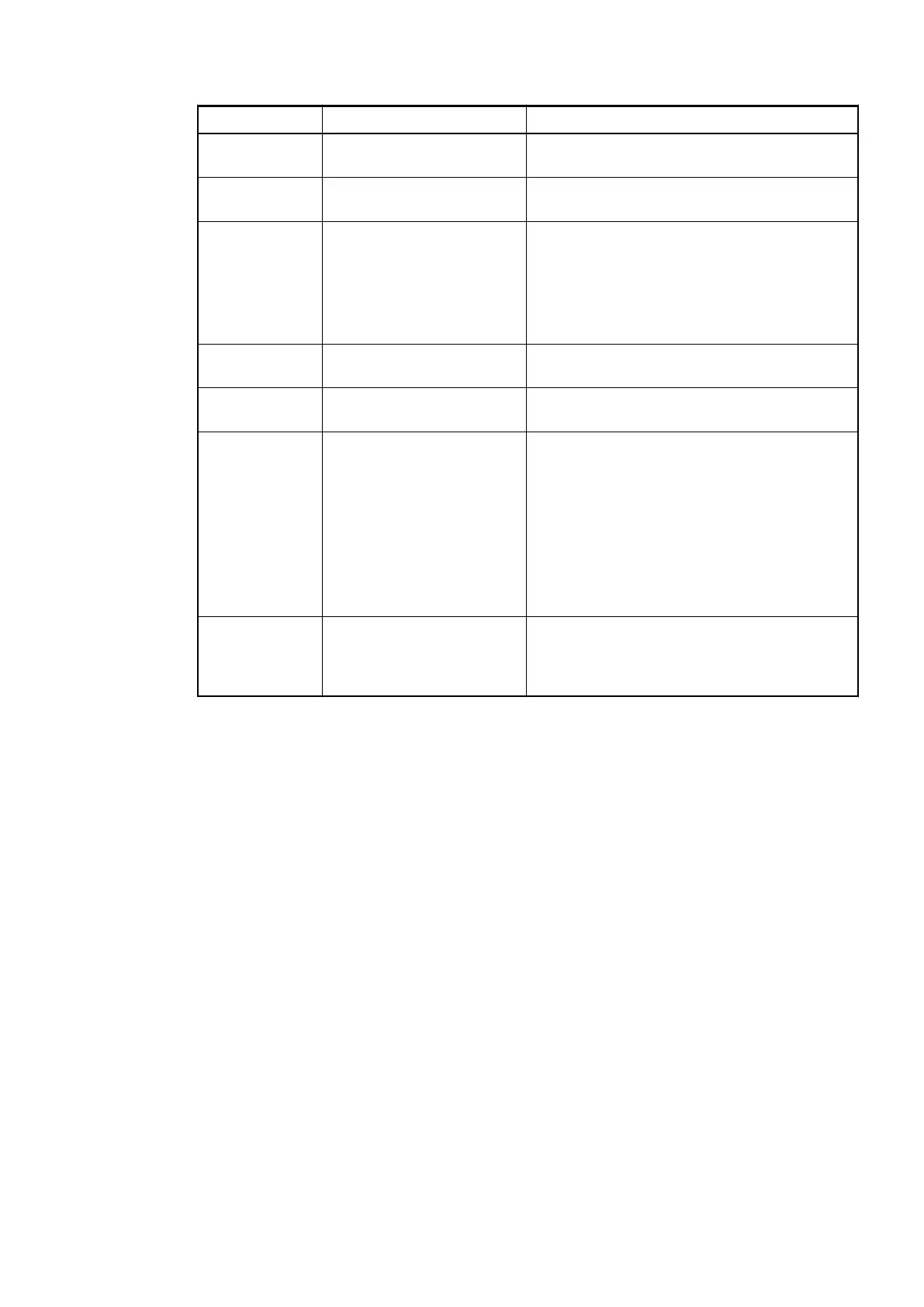
Byte Number Description Possible Values
1 Data length (header
included)
7
2 PROFIBUS DP V1 coding:
Vendor specific
129
3 Diagnosis Byte, slot number 31 = CI542-DP (e. g. error at integrated 8 DI /
8 DO)
1 = 1st connected S500 I/O module
...
10 = 10th connected S500 I/O module
4 Diagnosis Byte, module
number
According to the I/O bus specification passed
on by modules to the fieldbus master
5 Diagnosis Byte, channel According to the I/O bus specification passed
on by modules to the fieldbus master
6 Diagnosis Byte, error code According to the I/O bus specification
Bit 7 and bit 6, coded error class
0 = E1
1 = E2
2 = E3
3 = E4
Bit 0 to bit 5, coded error description
7 Diagnosis Byte, flags According to the I/O bus specification
Bit 7: 1 = coming error
Bit 6: 1 = leaving error
In cases of short circuit or overload, the digital outputs are turned off. The modules performs
reactivation automatically. Thus an acknowledgement of the errors is not necessary. The error
message is stored via the LED.
Communication Interface Modules (S500) > PROFIBUS
2019/04/17 3ADR010121, 13, en_US 993