5-10
Cisco ONS 15454 Procedure Guide, R5.0
December 2004
Chapter 5 Turn Up Network
NTP-A40 Provision BLSR Nodes
NTP-A40 Provision BLSR Nodes
Step 1 Complete the “DLP-A44 Install Fiber-Optic Cables for BLSR Configurations” task on page 17-52,
verifying that the following rules are observed:
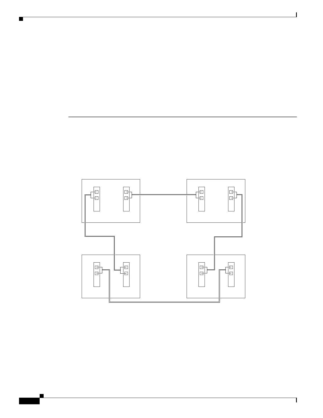
• Verify that the east port at one node is connected to the west port on an adjacent node, and this
east-to-west port connection is used at all BLSR nodes, similar to Figure 5-2. In the figure, the
OC-N drop card on the left side of the shelf is the west port, and the drop card on the right side of
the shelf is considered the east port.
Figure 5-2 Four-Node, Two-Fiber BLSR Fiber Connection Example
•
For four-fiber BLSRs, verify that the same east port to west port connection is used for the working
and protect fibers, similar to Figure 5-3. Verify that the working and protect card connections are
not mixed. The working cards are the cards where you will provision the DCC terminations.
Purpose This procedure provisions ONS 15454 nodes for a BLSR.
Tools/Equipment None
Prerequisite Procedures NTP-A35 Verify Node Turn-Up, page 5-2
Required/As Needed As needed
Onsite/Remote Onsite
Security Level Provisioning and higher
55297
Node 1
West East
West East
West East
West East
Slot 5
Tx
Rx
Slot 12
Tx
Rx
Node 4
Slot 5
Tx
Rx
Slot 12
Tx
Rx
Node 2
Slot 5
Tx
Rx
Slot 12
Tx
Rx
Node 3
Slot 5
Tx
Rx
Slot 12
Tx
Rx

 Loading...


