5-39
Cisco ONS 15454 Procedure Guide, R5.0
December 2004
Chapter 5 Turn Up Network
NTP-A48 Subtend a BLSR from a BLSR
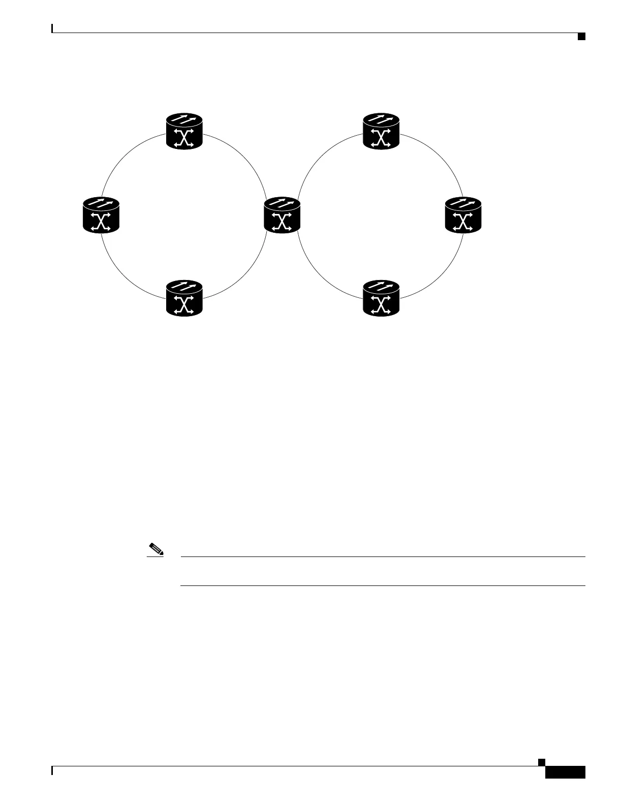
Figure 5-13 BLSR Subtended from a BLSR
Step 3 Attach fibers from the trunk cards in the subtending node to the BLSR trunk cards on its two neighboring
BLSR nodes. In Figure 5-13, Node 4/Slot 6 connects to Node 7/Slot 13, and Node 4/Slot 13 connects to
Node 5/Slot 6. See the “DLP-A44 Install Fiber-Optic Cables for BLSR Configurations” task on
page 17-52.
Step 4 Create the DCCs on the first OC-N card that will carry the BLSR. See the “DLP-A377 Provision Section
DCC Terminations” task on page 20-61. Alternatively, if additional bandwidth is needed for CTC
management, complete the“DLP-A378 Provision Line DCC Terminations” task on page 20-62.
Step 5 Repeat Step 4 for the second OC-N trunk card that will carry the BLSR.
Step 6 Complete the “NTP-A40 Provision BLSR Nodes” procedure on page 5-10 for each node that will be in
the BLSR. If you have already provisioned the BLSR, perform this procedure for the subtending node
only.
Step 7 If the subtending BLSR is not already created, complete the “NTP-A126 Create a BLSR” procedure on
page 5-12 to provision the new BLSR. The subtending BLSR must have a ring name that differs from
the ring name of the first BLSR.
Note The subtending node can have one Node ID that is used in both BLSRs, or a different Node ID
for each BLSR. For example, the same node can be Node 4 in BLSR 1 and Node 2 in BLSR 2.
Step 8 From the View menu, choose Go to Network View to see the subtending ring.
Figure 5-14 shows an example of two subtending BLSRs.
55298
Node 5
Slot 6
West
East
Slot 13
Node 7
Slot 13
East
Slot 6
West
Slot 6
West
Slot 13
East
Node 6
Node 1
Slot 5
West
Slot 5
West
Slot 12
East
Slot 12
East
Node 3
Slot 12
East
Slot 5
West
Node 2
Slot 5
West
Slot 12
East
Slot 13
East
Slot 6
West
Node 4
BLSR
Ring 1
BLSR
Ring 2

 Loading...


